Sand Control
Controlling high fines production in high-volume gas wells
Offshore wells receive multiple-path, concentric, annular, openhole gravel pack completions for laminated reservoirs.
S. Salahudin and K. King, Halliburton Energy Services, Inc.; J. H. Terwogt, N. S. Hadfield and A. T. P. Van Kranenburg, Sarawak Shell
Sarawak Shell’s offshore Shallow Clastics (SC) field has two shallow gas-bearing reservoirs, H1 and H2, at about 2,650-ft TVD. The reservoirs are a sequence of highly laminated sand and shale deposits with significant sand-size variability and high fines content. Since the reservoirs are unconsolidated, downhole sand exclusion is mandatory.
Log data, Fig. 1, from SC were gathered from the appraisal and development wells of the deeper carbonate gas reservoirs; however, core data were limited to a single, poor-quality core from Well E11-SC1. An appraisal/ early-producer well, E11-SC2, was drilled with a deviated wellbore through the H1 and H2 targets. Its completion design consisted of a cased-and – perforated, commingled completion inside 9-5/8-in. casing.
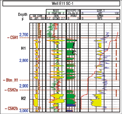 |
Fig. 1. Shallow Clastics field’s H1 and H2 reservoirs are a sequence of gas-bearing highly laminated, sand and shale deposits with sand-size variability and high fines.
|
|
The sand-face completion design consisted of a large-OD expandable sand screen with 150-µm weave opening across the zones. Upon completion, the reservoirs were cleaned through a temporary well cleanup and test facility to gauge productivity and evaluate the downhole sand-exclusion installation’s integrity. Fines production, possibly due to failure of the expandable screen, began almost immediately and increased steadily, so that the well could no longer produce.
INITIAL WELL DESIGN
The development plan for the SC reservoirs called for a phased, multi-well development from four locations. These included the existing E11 platform and the future F13 drilling platform. The existing gas gathering infrastructure has a low tolerance for solids production.
Prior to developing the first well, the development plan consisted of highly deviated (70°) wells with openhole expandable sand screens penetrating the H1 reservoir. Because the well produced fines to the surface, the operator re-evaluated the plan and well concepts.
SAND CONTROL COMPLETION
Engineers revisited the completion design, using the results from E11-SC2 along with core samples from well F13-6, a carbonate appraisal. The key challenges were to maintain planned well productivity (minimum 60 MMcfd per well) and ensure effective reservoir drainage.
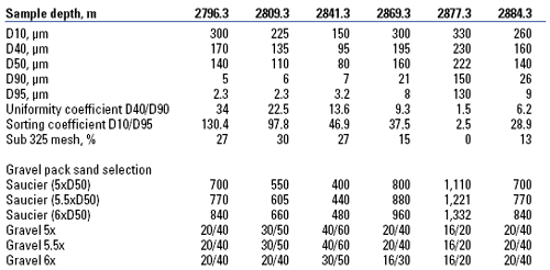
Analysis of the F13-6 core sample confirmed a smaller than expected sand-grain size (D50: 80-220 µm). The uniformity coefficient (D40/D90) varied between 1.5 and 34, indicating that the formation grain size is highly non-uniform, Table 1. Other indicators that affect the sand-control design have been suggested by George King, et al.1 Their approach suggests evaluating a sorting coefficient and percentage of fines (sub 44-µm particles) in the formation sample to help select the sand-face completion. Sorting coefficient (D10/D95) gives a broader evaluation of sand-size distribution. In the F13-6 core, this was 2.5 to 130, further confirming the highly non-uniform, sand-grain sizes.
| TABLE 1. Formation sand size distribution analysis and gravel pack sand selection (representative sample). |
 |
|
Fines content can reach 34%, which is considered very high when attempting to produce with minimal-to-no-solids production. Fines movement is influenced by flow velocity and associated drawdown. One way to minimize the production flow velocity is by wellbore in-flow area enlargement, either through fracturing or by drilling long, highly deviated or horizontal openholes (OH) through the pay zone. Increasing inclination through the pay from 70° to 80° will double OH surface area and reduce flow velocity by half. Further increasing the inclination to 88° will increase OH surface area ten-fold, resulting in 1/10th the flow velocity. Another advantage of a longer OH is a significantly higher production potential.
SAND-CONTROL METHODS
Sarawak Shell undertook a full qualitative evaluation of sand-control methods for an enlarged in-flow area wellbore completion. The evaluation included expandable screens, alpha-beta horizontal OH gravel pack (HZ OHGP), alternate path horizontal OH gravel pack (AP-HZ OHGP) and frac pack. Factors considered were installation record, suitability for highly non-uniform, sand-size distribution, productivity and lifecycle cost. Limitations on well path and the effect on reservoir drainage were also considered. Weighting was applied to each of the attributes to arrive at a total weighted score. Stand-alone screens were not considered because of the large variability in sand-size distribution that would not be retained by them.
OH expandable sand screens scored poorly for this application because of their inability to minimize fines production at surface. Frac pack, while applicable, would require more wells for effective reservoir drainage.
Alpha-beta HZ OHGP scored well as a sand-control method. However, the large shale intervals raised concerns on obtaining a complete GP. The addition of an alternate-path system to the OHGP method would minimize this risk and enhance the ability to achieve a complete GP. AP-OHGP ranked the highest of the options, since it had a greater probability of ensuring an even and complete gravel pack over the entire openhole length and reduced early screen-out over the reservoir’s shale intervals.
Both multiple path alpha-beta HZ OHGP and shunt-tube OHGP were evaluated. The multiple-path HZ OHGP method, employing a concentric annular gravel-packing system, was selected for its flexibility, large screen ID and the future ability to eliminate elements of the concentric annular packing system.
A model for expected well inflow performance was developed. A skin of +10 was assumed over the reservoir as the base case. Well production of over 80 MMcfd was expected, based on this model. Initial well rates were limited to 60 MMcfd because of the velocity erosion potential with a fines production rate of 0.05 g/s. These constraints were to be reevaluated once the sand-control system and the wells were reviewed.
FINAL COMPLETION DESIGN
The final completion design used highly deviated, (~80°) 8-1/2-in. boreholes through the pay completed with an OHGP. To minimize the risk of an incomplete GP, a multiple-path concentric annular gravel-packing (MPCAGP) system was used.
The MPCAGP system consisted of 4-1/2-in. 12.6-lb, wire-wrapped screen and blank GP assembly inside a 7-in. 17-lb, specially perforated shroud. The expendable, perforated shroud was made of L-80 high-alloy steel.
GP sand selection used Saucier’s criteria, Table 1. For poorly sorted sands with a high level of fines, a gravel/ sand D50 size ratio of 5 is recommended; thus, 30/50 mesh gravel was selected. An 8-gauge, GP screen-slot was selected to retain the sand.
The upper completion design included a 7-in. anchor latch that locates in the GP packer, a disappearing plug, an autofill device and a landing nipple below a production packer. A permanent pressure-gauge assembly, 7-in. tubing, 7-in. subsurface safety valve and 7-in. tubing completed the string above the production packer to the wellhead, Fig. 2. All completion assembly components were 13-chrome steel, to mitigate corrosion from the small amount of CO2 expected.
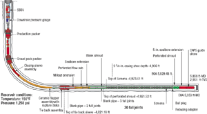 |
Fig. 2. The completion design gives installation simplicity, a production large bore, downhole pressure monitoring and access to the sandface completion for future well interventions.
Click image for enlarged view |
|
The design gave installation simplicity, a large bore for production, permanent downhole pressure monitoring and access to the sandface completion for future well interventions.
MPCAGP SYSTEM
The MPCAGP system enhances highly-deviated and horizontal OH alpha-beta gravel packing by providing additional flow paths between the OH and the screen through a specially perforated shroud. The perforated shroud allows the slurry to bypass bridges or hole collapse and high leak-off areas that may occur as a result of shale instability, wellbore size variations or high-permeability areas.
The shroud dimension and perforation diameter, quantity and distribution are optimized by physical and numerical modeling to enable slurry movement between the outer two annuli, Fig. 3. During gravel packing, flow is split between the three annuli with the slurry transported along the outer two annuli, OH/ shroud, and shroud/ screen. The sand-free carrier fluid is transported along the screen/ wash pipe annulus. With no annular flow restriction, the outer two annuli will act as one annulus. When an annular blockage occurs in one annulus, the fluid flowing in that annulus is automatically re-routed to the other annuli, increasing the flowrate and pressure in those annuli. This pressure increase in the open annuli forces fluid back into the diverted annulus once the fluid is past the bridge and the pressure tries to fall to the lowest level. The fluid flow in the respective annuli will reapportion itself, and the alpha wave packing will continue to the toe.
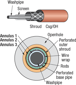 |
Fig. 3. The perforated shroud allows the slurry to bypass bridges, hole collapses and high leak-off areas.
|
|
COMPLETION PLANNING
Early in the project’s implementation cycle, the operator’s project team recognized their limited experience, so selecting the sand-control service provider became important. Emphasis was placed on key success factors:
Experience and project management. The project coordinator had experience in similar installations, and assisted in the design, procurement, preparation, testing, execution, and optimization of the completion installation process.
Stable and gauge OH. Ensuring a stable and gauge OH was critical to a complete gravel pack. Several drilling elements were considered:
- Casing setting and rat hole. The last casing was to be set in the pay and as close to bottom as possible to minimize rat hole.
- Drill-in fluid selection and maintenance. Based on the operator’s experience, a water-based reservoir Drill-In Fluid (DIF) with sized CaCO3 particulates for fluid-loss control and density was selected.
- Optimize drilling assembly. The well tracks were planned to minimize dogleg severity and reach the target (80° inclination in the 12-1/4-in. hole section), which was held to casing point, and in the 8-1/2-in. section, to TD. A steerable-motor assembly drilled the 8-1/2-in. OH sections because it delivers a fairly consistent wellbore gauge.
Wellbore and completion fluid cleanliness. To reduce formation damage, a casing cleaning process removed oil-based-mud and scale. Solids-free fluid and completion brine filtration used low Nephelometric Turbidity Units (NTU) with diatomaceous earth filtration.
Filter cake. Maintaining an intact filter cake throughout the gravel-pack process was necessary and accomplished by constant hydrostatic pressure in the OH, using the flow paths in the service tool.
INSTALLATION OPTIMIZATION
Once the success factors were identified, the focus turned to installation optimizing. An area with optimization potential was the filter cake removal process. Previous methods required additional rig time, often removed filter cake unevenly, and exposed the well to significant fluid loss.
The optimized approach employed two new technologies; a single-trip GP and treat system, which allows pumping access through the washpipe after completion of the GP, and a delayed filter cake breaker system. By removing the secondary clean-up activity and the traditional acid system, post GP filter-cake-removal risks were mitigated and completed with one trip. This saved over 18 hrs of completion time per well.
FILTER CAKE REMOVAL SYSTEM
The DIF contained starch for filtrate control, xanthan as a viscosifier, and CaCO3 particulates as the fluid-loss and weighting material. The filter cake that forms on the borehole wall provides leak-off control, and its density provides borehole stability. Once gravel packing is completed, previous experience has shown2 that filter cake removal is required and has an effect on productivity. In the past, cleaning up the filter cake posed several challenges:
- Additional rig time for a trip
- Additional service costs and rig time or deferment costs where coiled tubing was used
- Uneven filter cake cleanup across the OH because of the HCl used
- Completion-fluid losses during acid washing and tripping out of the wash pipe to close the mechanical fluid-loss-control device posed well-control issues and contributed to nonproductive time and formation damage.
Certain DIFs require enzymes or oxidizers to enhance filter cake cleanup. The oxidizer helps degrade the starch and xanthan polymer binding the CaCO3, while the organic acid attacks and dissolves the CaCO3. Placement of the delayed breaker system is either with the fluid during GP, requiring large volumes of fluid, or is spotted inside the screen ID after GP.
Laboratory testing optimized the breaker recipe for the DIF, determined the delay and cleanup characteristics. For this application, a minimum 1.5-hr delay was needed to place the breaker fluid, remove the pumping connections on the workstring, pull the GP BHA, and close the fluid-loss flapper valve.
DELAYED BREAKER TESTING
A delayed breaker system placed with the GP or inside the GP screens and left to permeate and dissolve the filter cake over time eliminates these risks of completion-fluid losses. Delayed breaker systems generate acid over time and temperature by hydrolyzing an ester in the presence of water to alcohol and an organic acid. Acid generation can be delayed, allowing time to retrieve the GP assembly and close the fluid-loss valve. The delayed system has a low corrosion level on downhole sand-control hardware and lower risks to personnel at the surface.
Laboratory testing determined the required delay and the regained permeability expected. A three-part testing schedule was developed. The first part confirmed miscibility of delayed breaker materials in the completion brine. The second part determined the reaction delay for the filter cake, and the third determined the regained permeability and cleanup efficiency.
The delayed breaker materials were not completely miscible in the calcium chloride completion fluid. This was resolved by using a small volume of sodium bromide brine as the base fluid for the delayed breaker solution.
Breaker delay was tested using the modified dynamic filtration device described in SPE 689685 along with the proposed DIF recipe for drilling the OH. The test showed that a 3-1/2-hr delay is achievable.
Regained permeability tests were performed to determine filter cake removal efficiency with the delayed-breaker formulation. The regained permeability test, Fig. 4, showed that the formulation resulted in about 75% regained permeability. Although 100% regained permeability was not achieved, long OH completions do not require a very high regained permeability to achieve low skin.
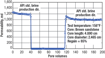 |
Fig. 4. The delayed breaker formulation resulted in about 75% regained permeability.
|
|
FIELD IMPLEMENTATION
The first four wells in the development were drilled and completed between November 2004 and June 2005. They were the first highly-deviated, MPCAGP OH completions in Malaysia and for Shell. This was also the first implementation of the single-trip-GP-treat-tool system and delayed breaker system in Malaysia and for Shell.
All four wells were drilled using the same procedure. The 12-1/4-in. upper-hole sections were drilled with an oil-based mud, and the hole angles were built gradually to 80° and held to section TD about 20 ft into the top of the H1 formation. The 9-5/8-in. casing was then run and cemented, leaving minimal rat hole. Prior to drilling out the 9-5/8-in. shoe, casing brushes were run and the casing was chemically and mechanically cleaned. The casing shoe and rat hole were drilled-out with viscosified weighted sea water and circulated clean. Fresh-water-based DIF was circulated, and the OH sections were drilled to TD.
DIF density in the first well was maintained at 0.58 psi/ft for hole stability. Experience from this well encouraged a lowering of the drill-in fluid density to 0.53 psi/ft. No detrimental hole stability problems resulted.
OH lengths ranged from 831 ft to 1,104 ft. After the OH section was drilled to TD and circulated clean, a short trip was made into the 9-5/8-in. casing shoe and the casing was circulated clean. The drilling assembly was then run back to TD without rotating or reciprocating as a check of hole stability and cuttings bed, as well as to simulate running the concentric annular gravel-packing-system assembly to bottom. On bottom, the hole was displaced with three openhole volumes of viscosified brine, the same density as the DIF at an annular velocity of 300 ft/min. The BHA was pulled inside the 9-5/8-in. casing shoe and the casing was displaced to clean the viscosified brine.
There were no drilling problems or losses when drilling the OH sections in the first three of the four wells. In the fourth well, DIF loss was encountered, which was overcome with reduced fluid density of 0.48 psi/ft and increased CaCO3 concentration. Despite DIF changes, losses of 25% persisted; but these did not affect running of the concentric annular packing system assembly or the gravel pack placement.
MPCAGP INSTALLATION
Due to the presence of long shale sections in the pay zones, an early design decision was made to run the concentric annular GP system as a two-trip system: the perforated shroud is run and set in the first trip followed by the GP assembly. The concentric annular packing system shroud assembly was designed with an internal washpipe to allow wash down and, if needed, rotation.
The concentric annular packing-system assembly consisted of 7-in. perforated pipe, centralized with an 8-1/4-in. OD centralizer located mid-joint and pin-end of each joint. The upper part of the assembly included a tie-back sleeve assembly, including a perforated flow sub and sealbore. The tie-back sleeve contained no slips or elements and was designed as a deployment tool for the concentric annular packing system shroud assembly. The perforated-flow sub and sealbore provided a positive depth location for the GP assembly and helped ensure that the slurry would be diverted to the outer annulus before the perforated shroud was reached, where the slurry would be reapportioned to both outer annuli.
On all four wells, the concentric annular packing system shroud was positioned from 30 ft to 70 ft into the casing shoe. When the GP assembly was run, the top of the screen was about 90 ft below the top of the perforated shroud and about 50 ft below the casing shoe. These depths ensured good laminar slurry flow before entering another annulus in the flow path.
Once the concentric annular packing system shroud was at TD, the OH was displaced with clean, filtered completion fluid (NTU<20) at an annular velocity of 300 ft/min. The tie-back sleeve running tool was then released, and the casing was then displaced to completion brine.
Based on the operator’s experiences, no sacrificial screen was run for any of these wells. This allowed the operator to have screens for production all the way to section TD. The GP assembly consisted of 8-gauge 316L wire-wrapped screens with bladed centralizers, blank pipe, casing extensions, indicator couplings, MCS closing sleeve, and a large-bore GP packer. The bladed centralizers kept the screen centralized in the shroud and facilitated gravel placement around the screen.
The shroud, screen, and washpipe dimensions were considered in the overall design for GP placement. The 3-1/2-in. wash pipe used inside the screen gave a 0.88 OD/ID ratio inside the 4-1/2-in., 12.6 lb screen and a flow area of 2.68 in2. The flow area in the 7-in. concentric annular-packing-system shroud within the 8-1/2-in. openhole resulted in 52% flow across the outer annulus, 38% in the middle and 8% in the inner annulus, which was considered optimum.
The hole condition enabled the concentric annular-packing-system shroud to be run to TD without washing down or rotating the assembly. The OD/ID optimization between the shroud and tie-back assembly with the OH and casing enabled all circulations to be completed as planned with velocities reaching the minimum recommended 300 ft/min.
GRAVEL-PACK PLACEMENT
GP placement was simulated using both operator and service company software. It took into account wellbore trajectory and geometry, sand-control completion hardware, brine and GP carrier-fluid properties, sand type proposed, estimated fluid-loss regime during placement and expected fracture gradient to determine the following parameters:
- Optimum pumping rate for the desired alpha-wave sand height
- Predicted surface pumping pressure for the pumping rate
- Expected bottomhole treating pressure
- Total sand volume and time required
- Minimum slurry spotting and reverse-out rates
- Maximum bottomhole treating pressure.
The simulation showed that the jobs could be placed at reasonable pump rates even with a low return rate of 50%, and that the job could be completed to screen-out. Once the GP assembly was in place and tested, circulation tests were performed in all four wells with the GP tool in the reverse and weight-down circulate position. This was to determine the friction pressure in the workstring and through the entire system, as well as the return rate.
This information then calibrated the model and generated updated placement schedules and expected pumping pressures. Formation fracture gradient was obtained on the first well, E-11 SC-3. After drilling to TD, the drilling assembly was pulled back to the casing shoe, and a leak-off test was performed yielding 351 psi or 0.69 psi/ft leak-off gradient. The DIF afforded almost 100% returns during the circulation test except for the fourth well, which had only 76% returns.
GP were emplaced at 4.5 bbl/min to 5 bbl/min, laying the initial alpha wave to 80% of the screen height. Sand concentration was maintained between 0.75 to 1.1 ppa throughout the job, and clear beta waves were observed, Fig. 5. All wells achieved 97% or better pack efficiency, based on an estimated 8-1/2-in. diameter OH, Table 2. In the first well, screen-out pressure was not observed, even after 100% of the sand volume was pumped. There were clear screen-out pressures at the end of wells, two, three, and four, showing effective packing into the casing shoe.
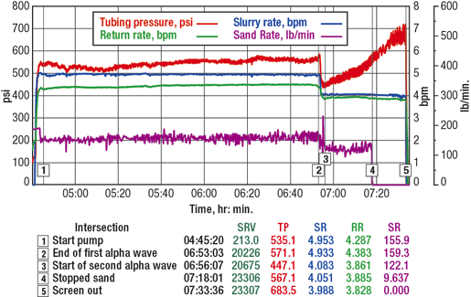 |
Fig. 5. Gravel packs were emplaced at 4.5 bbl/min to 5 bbl/min, laying the initial alpha wave to 80% of the screen height; clear beta waves were observed.
|
|
| TABLE 2. Summary of gravel pack placement and pack efficien |
 |
|
FILTER CAKE REMOVAL
Upon successfully completing the gravel pack, the service tool was converted to a wash-down configuration by dropping a ball to open the diverter sleeve and deactivating the pressure-activated ball check. The required volume, screen-ID volume plus 25% excess of delayed breaker with oxidizer was then mixed and placed inside the GP screen. The tool was then pulled to the fluid-loss flapper valve, where a shifter engaged and closed the valve.
In the first well, 80 bbl/hr losses were encountered, once the breaker solution was placed. Losses slowed to 50 bbl/hr, which allowed the service tool to be pulled and the fluid-loss flapper valve to be closed. It is believed that delays in mixing and placing the breaker fluid exceeded the tested delay, and placed live acid across the screen ID.
In wells two, three and four the maximum delay obtainable from laboratory testing was one hour. The results showed that the DIF starch was causing inconsistent results. The decision was made to proceed with placing the delayed breaker, despite the results, with the understanding that all effort would be made to safely mix, place, pull out, and close the flapper within that time.
WELL CLEANUP AND TESTING
Each of the wells was cleaned up and tested through a temporary test facility. The objectives were to confirm the well productivity and performance of the sand control design to minimize sand production. The test package consisted of a sand filter, choke manifold and inline erosion probes. Rate measurements were based on the choke equation.
For the first well, a conservative bean-up approach was used to allow particle bridging in the gravel pack, Fig. 6. This figure shows the solids production as a function of choke size as the well was beaned-up to a final production rate of 60 MMcfd. Flush solids production after each bean change tailed-off as the particles were retained by the gravel pack. Final solids production at 60 MMcfd was less than 0.05 g/s, indicating that the rate limitation of 60 MMcfd, imposed by erosional velocity constraints, could be further reviewed. Figure 7 shows the test results at the perforations compared to modeled inflow performance relationships. These indicated better-than-expected inflow performance.
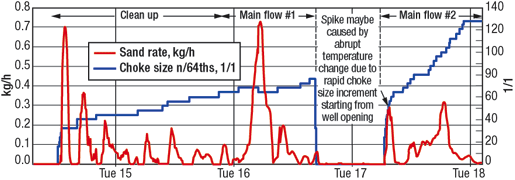 |
Fig. 6. This graph shows the solids production as a function of choke size while the well was beaned-up to a final production rate of 60 MMcfd.
|
|
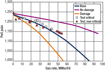 |
Fig. 7. Test results at the perforations compared to modeled inflow performance indicates better-than expected inflow performance.
|
|
LESSONS FOR FUTURE WELLS
Key learnings gained were captured for future use. Additional testing of the delayed breaker system is required, given the inconsistent results. Changing to another delayed breaker system for future wells should be considered.
Assess possible time savings from circulating the OH directly to brine with the drilling BHA instead of the viscous-brine intermediate step, if hole conditions permit. Maintain fluid densities, when drilling the OH section and when switching from drill-in fluid to viscosified brine. Reduce fluid-density risks when lifting off the filter cake.
Evaluate deploying concentric annular gravel-packing system shroud and gravel-pack assembly in a single trip. This could result in time savings or the elimination of the concentric annular packing-system shroud.
Hole conditioning upon drilling to TD was well worth the extra time taken to circulate and swap fluids before running the concentric annular-packing-system BHA. The shroud BHA was run to TD without any difficulty.
Fluid cleanliness is the key to minimizing formation damage. In all four wells, filtration maintained the viscosified brine and brine to <20 NTUs.
The pressure-activated ball check has variability when deactivating for the post GP filter cake removal treatment. The time taken to deactivate ranged from 30 min. to 2 hr. To simplify operations, implement a multi-acting reverse valve in place of the pressure-activated ball check. This tool does not require pressure to deactivate and works off a collet system, allowing positive verification at each step.
CONCLUSIONS
The revised well and sand-control completion design met the field-development planned production objectives and no sand production was observed during post completion cleanup and testing. Fines production was minimal and stabilized to a low value during the post completion cleanup and testing. This allowed a higher production potential to be realized.
Post completion cleanup and testing showed a low completion skin <+5. Minimal non-productive time and no lost-time injuries were recorded for the completion phase of the project.
By applying lessons learned and improving operations during the first three wells, the fourth well was completed and placed online one year ahead of schedule. The technologies employed resulted in cost and time savings of approximately one day per well. 
ACKNOWLEDGEMENTS
The authors thank the management of Sarawak Shell, Petronas and Halliburton Energy Services, Inc. for permission to publish this paper. In addition, the authors give special thanks to the field operations personnel, who made the operations successful. This paper was presented at the Petroleum Society’s 7th Canadian International Petroleum Conference (57th annual), Calgary, Alberta, Canada, June 13 – 15, 2006.
LITERATURE CITED
1 Tiffin, D.L. and G. E. King., R. E. Larese, L. K. Britt, "New criteria for gravel and screen selection for sand control," SPE 39437, presented at the SPE Formation Damage Control Conference, Lafayette, Louisiana, February 18 – 19, 1998.
2 VanVliet, J.P.M., and H.C. Lau, O.B. Skilbrei, S. H.A. Rahman, L.A. Bernardi, E.E. Shumilak, A.S. Halal, "Horizontal openhole gravel packs boost oil production in Brunei," SPE 72130, presented at the SPE Asia Pacific Improved Oil Recovery Conference, Kuala Lumpur, Malaysia, October 6 – 9, 2001.
3 Dickerson, R.C. and O. Ojo-Aromokudu, A. A. Bodunrin, K. Passant, T. Roane, Penno, H. Fitzpatrick, "Horizontal openhole gravel packing with reactive shale present – a Nigeria case history," SPE 84164, SPE Annual Technical Conference and Exhibition, Denver, Colorado, October 5 – 8, 2003.
4 Sanders, M.W. and H.H. Klein, P.D. Nguyen, D.L. Lord, "Gravel-pack designs of highly-deviated wells with an alternative flow-path concept," SPE 73743, International Symposium and Exhibition on Formation Damage Control, Lafayette, LA, February 20 – 21, 2002.
5 Todd, B. and R. Murphy, "Laboratory device for testing of delayed-breaker solutions on horizontal wellbore filtercakes," SPE 68968, SPE European Formation Damage Conference, The Hague, Netherlands, May 21 – 22, 2001.
|
THE AUTHORS
|
| |
Sharifudin Salahudin is a senior technical sales advisor in Halliburton’s Global Business and Technical Solutions group in Houston. He has 25 years of operations and technical experience.
|
|
|
Kimberly A. King is a senior technical professional with Halliburton based in east Malaysia. She has over eight years industry of experience in deepwater projects. King earned a BS degree in ocean engineering.
|
|
|
Jan H. Terwogt is a well engineer with Shell Malaysia Exploration & Production and has worked for Shell since 2000. Terwogt earned an MS degree in mining and petroleum engineering from Delft University of Technology in 1994.
|
|
|
Neil Hadfield is a senior production technologist with Shell Malaysia Exploration & Production and has worked for Shell since 1997. Hadfield earned an ME degree in chemical engineering from Bath University, UK, in 1997.
|
|
| |
Aart van Kranenburg is a production technologist at A/S Norske Shell as a sand control specialist. He has designed and installed sand control and fracpack completions around the world. Kranenburg earned an MS degree in mining and petroleum engineering from the Delft University of Technology.
|
|
|


