|
Vol. 227 No. 3 |
| |
 |
Understanding wax problems leads to deepwater flow assurance solutions
Interpretation of lab measurements provides pigging and treating rules of thumb.
Thomas S. Golczynski and Elijah C. Kempton, Multiphase Solutions, Inc.
Increased exploration and production activity from the world’s deepwater fields have brought flow assurance issues to the forefront. Concerns about wax deposition, wax gelation and hydrate formation play a significant role in concept selection for deepwater and ultra-deepwater development projects. Water depth, long distances from the reservoir to the host facility via subsea tiebacks, dry tree risers and extended export pipelines in cold ambient water temperatures all pose risks for operators to consider when planning their development scenarios. Under these adverse conditions, it is important to understand multiphase fluid properties and the design options to prevent or mitigate deepwater flow assurance challenges. This article focuses on wax-related problems.
WAX DEPOSITION AND GELATION
Wax deposition and wax gelation are two potentially catastrophic issues in crude oil and gas/ condensate systems that can render a pipeline unusable. While typically confined to oils, gas/ condensate discoveries in Southeast Asia have shown waxing and/or gel formation.
The deposition of n-paraffin will commonly occur along the pipe walls when the temperature of produced fluids falls below the Wax Appearance Temperature (WAT) or cloud point, the point at which the first wax crystals start to precipitate out of solution. Deposition rates can be attributed to many factors including paraffin content, fluid viscosity, flowrates, gas/ oil ratio and the heat transfer coefficient (U-value).
Wax gelation is less common in steady-state than is wax deposition, but it can have even greater impact if, during production system shutdowns, fluid temperatures cool below the fluid pour point, allowing the formation of a “candle” or solid wax column. This condition can completely block the pipeline. During restart operations, there might not be sufficient pressure available at the pipeline inlet to “break” the gel and allow the pipeline to flow. The pipeline, at that point, may be rendered useless.
LABORATORY MEASUREMENTS
Laboratory measurements are important in establishing predictive models to determine wax deposition rate and degree of wax gelation. In both instances, interpretation of the data and understanding of the testing procedures are critical.
Wax deposition. The WAT is perhaps the most important laboratory measurement for determining the extent of the wax deposition problem in the subsea system. It is essential to understand the difference in test results that can be obtained by using live oil versus stock tank oil.
Typically, stock tank measurements are conducted (with a redundancy recommended to ensure consistency in the results) to evaluate the severity of the problem. For most systems, the stock tank oil WAT is the design point that is commonly used, but it is inherently conservative. Stock tank oil samples are typically much more readily available than live oil samples. Under normal (live) production conditions, the actual WAT may be some 10°C (50°F) lower, as light-ends dissolve into solution with increased pressure, effectively reducing the WAT.
When designing a production system, consideration must also be given to the temperature required to re-dissolve any wax that forms. Because of the kinetic effects of deposition, wax doesn’t always return to solution once temperatures are elevated above the WAT. Instead, production fluid temperatures might need to be elevated 20°C (68°F) or more above the WAT to melt any wax that has deposited.
Viscosity has a major impact on the wax deposition rate. As viscosity increases, wax deposition rates decrease because wax particles diffuse less easily to the pipe wall. Therefore, care needs to be taken if chemicals are injected to reduce viscosity for hydraulic performance improvement, as these chemicals might increase the wax deposition rate.
Determining the deposition rate is perhaps the most complicated of the paraffin-related laboratory tests, with multiple ways of quantifying the rate. The goal of each method, however, is to determine the deposition rate to the pipe walls. Because the wax deposition rate is governed to a large degree by the temperature gradient between the production fluid and the ambient surroundings, there must be a positive heat flux across the pipe. If the fluid temperature reaches ambient conditions, or falls below ambient conditions, no wax deposition will occur.
Analog data, based on known fluid properties, can also be used to estimate wax deposition rates. Using this key information and comparing it with the deposition properties of similar fluids within geographic proximity can provide a close match against the fluid in question. It can also be used to infer the deposition rate in lieu of laboratory testing. To utilize this approach, however, it is imperative that all key parameters – including WAT, viscosity, API gravity, molecular weight and wax content – be considered to accurately determine the deposition rate. As Fig. 1 illustrates, two fluids with similar WATs can have different wax contents and deposition rates because of varying viscosities and other factors. It is, therefore, necessary not to rely solely on only one fluid property for fluid matching.
 |
Fig. 1. Two fluids with similar wax appearance temperatures can have different wax contents and deposition rates.
|
|
Once the wax deposition rate is measured and interpreted, the results can be entered into a fully integrated, thermal model for predicting the location of any deposit, the deposit thickness as a function of time, the net pressure drop increase and the total volume of wax needing removal during pigging operations.
The modeling will assist operators in determining the pigging frequency needed for a specific field configuration. In general, wax deposition models are conservative, over-predicting wax deposition rates. The results from the models should be used as a guide to pigging frequency, with operations fine-tuning the actual pigging program as the field comes onstream.
Pigging frequency can be determined by using the deposition rate prediction and various rules of thumb, including:
- Limiting pressure drop across the pig to 50 – 100 psi
- Limiting total wax volume in front of the pig to 50 bbl
- Limiting total wax thickness to ~10% of the cross-sectional area
- Limiting total wax thickness to ~1 – 4 mm, depending on the deposition rate.
The last rule of thumb depends to a large extent on pipeline U-values. A fast deposition rate with high U-values (i.e., bare pipe) is often softer and easier to remove, with higher concentrations of oil. This condition can permit the operator to pig when the thickness reaches 4 mm. Conversely, slow deposition rates with low U-values (i.e., pipe-in-pipe) produce deposits that are usually harder (because they are more highly concentrated with high carbon number paraffins) and require pigging at 1 – 2 mm thickness to prevent the pig from becoming stuck in the pipe.
Wax gelation. Pour point is a principal factor in gel formation, as it defines the temperature gels form. For example, during a long shutdown after the production fluid has cooled to ambient temperatures, a pipeline can become completely blocked or present significant difficulties when being restarted.
In laboratory measurements, the pour point is the temperature at which the fluid no longer moves once inverted in a sample container. The pour point measurement is highly susceptible to cooling rate, with fast rates predicting higher pour points than slow cooling rates. Therefore, the cooling rate used in the laboratory should match closely with the anticipated cooling rate in the field, based on the insulation expected.
Laboratory tests are usually conducted on a tank stock or, preferably, a live oil sample cooled at a given rate and tested periodically at certain temperatures to determine whether or not it will flow. The pour point measurement, as with the WAT measurement, is pressure related and, as gas is added to the fluid, the pour point decreases.
If the fluid has a pour point below ambient seabed temperatures, typically no additional testing is recommended. If this is not the case, the cooling rate and pressure effects are more important and need to be evaluated further.
While pour point testing helps identify the risk of restart problems, yield (or gel) strength tests are useful in determining the pressure required to break the gel during restart. The wax candle need not yield in its entirety for restart to occur, as generally a “domino effect” will occur at significantly lower restart pressures.
Pour Point Depressant (PPD) might be required for continuous system treatment when the pour point is above seabed ambient temperatures and restart pressures are excessive. PPD may be selected to either reduce the pour point below ambient temperature or, in cases of very high dosages or high pour points, to reduce the restart pressure below acceptable levels.
In these cases, a gel may still form, but it would be weak enough to break easily. Additionally, PPD might have an adverse impact on wax deposition rates. Therefore, if PPD is utilized, laboratory testing should be completed to verify that PPD will also reduce wax deposition rates.
FIELD CONDITIONS
Once there is a basic understanding of the challenges associated with wax deposition and wax gelation risks and how they can be identified in the laboratory, it is necessary to apply this information to paraffin-related issues in the field.
Dry tree risers. It is generally assumed that dry tree risers have fewer flow assurance issues than subsea tiebacks, as they provide easier access (direct vertical) to the reservoir and production system. In deepwater and ultra-deepwater projects, however, insulating dry tree risers to prevent wax and hydrate problems can be a challenge.
Wax deposition. Under steady-state conditions, where the fluid arrival temperature is below the WAT, wax deposition can occur in the tubing string. The problem then becomes how to remove the deposit. Remediation options include insulation to maintain fluid temperatures above WAT, chemical inhibition and physical/ mechanical means, such as scraping the tubing.
External insulation, low-pressure annulus gas and/or gelled fluids in the annulus can be used to maintain temperature. With single-casing risers, care needs to be taken when gas and liquids are used as insulation, as natural convection within the fluids can greatly degrade the dry tree riser’s thermal performance.
Wax deposition rates can be reduced by continuously injecting a paraffin inhibitor. However, to be effective, a paraffin inhibitor should be injected at a temperature of 10°C (50°F) above the WAT. This may require deep-set injection mandrels in the well. Active heat may also be used to maintain a temperature above WAT. For these cases, it is advisable to consider the temperature required to melt the deposited wax, when designing the active heat system.
Wax gelation. Maintaining fluids above the pour point is critical. The cooldown time to the pour point might be very short, as little as four to six hours. With multiple well configurations, the scenario is complicated, as the operator must treat all wells. For large, multi-well developments, this may require simultaneous operations.
Operating procedures must be initiated to shut in wells once the flow rate drops below the rate needed to maintain cooldown time. As the profile in Fig. 2 shows, fluid temperatures can drop precipitously in a short period during a dry tree riser shutdown.
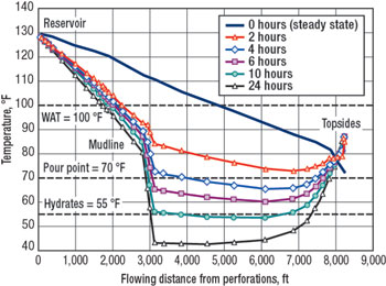 |
Fig. 2. Fluid temperatures can drop precipitously in a short period during a dry tree riser shutdown.
|
|
PPD injection, if used continuously, will help retard gel formation. As with a typical paraffin inhibitor, the PPD should be injected at some margin above the WAT/ pour point. Active heat could be used during a shutdown to maintain temperature and re-melt the gel prior to restart. Lastly, displacement of produced fluids back in to the formation using an inert fluid (other than dead oil) is also a possible solution to gelation.
Subsea tiebacks/ export pipelines. Typical wax-related control practices in deepwater subsea developments are insulating the flowlines, providing a looped system for round-trip pigging or utilizing continuous paraffin inhibitor to reduce the rate of wax deposition.
The economic impact of a subsea flowline blockage is considerably greater than with dry tree risers. While the lower achievable heat transfer coefficients (U-value) of subsea tiebacks might suggest improved thermal performance, this alternative might be cost-prohibitive with lengthy tiebacks. As with dry tree risers, any paraffin inhibitor must be injected at 10°C (50°F) above the WAT, which may require downhole injection. Thus, the subsurface/ completion design of the tubing will be impacted by the wax management strategy.
Wax deposition. Looped flowlines allow for pigging options; however, the cost of lost production time for round- trip pigging, as well as the cost of a second line to create the piggable loop, may outweigh insulation and chemical inhibition costs. Variables that must be considered are tieback length, pig velocity and nominal production rate. The insulation costs to lower the U-value (with a pipe-in-pipe solution, for instance), or inhibitor costs, must be analyzed against the savings of less-frequent pigging.
Wax deposition modeling is valuable in determining the likely location of wax buildup and in recommending a suitable insulation and pigging frequency program. Fig. 3 depicts the impact of paraffin buildup in a subsea tieback on its temperature profile and wax thickness, respectively. Fig. 3, top, shows the temperature of an uninsulated pipeline over time (as wax deposition occurs). The profile quickly drops toward ambient, but wax buildup actually provides insulating properties, thus extending the temperature profile. Fig. 3, bottom, shows a high wax buildup rate near the pipeline inlet. As the wax deposits and the insulating properties of wax make the temperatures warmer, the wax deposit location moves further down the pipeline. Once ambient temperatures are reached, there is no wax buildup.
 |
Fig. 3. (Top) An uninsulated pipeline’s temperature drops toward ambient, wax buildup insulates, extending the temperature profile. (Bottom) As wax is deposited, its insulating properties make the temperatures warmer and move the deposit further down the pipeline.
|
|
Wax gelation. The plugging of a subsea pipeline with gelled paraffin could be catastrophic. A looped flowline might be required to allow produced fluid displacement to remove all of the in-situ production fluid prior to gel formation. The insulation selected should provide sufficient cooldown time for non-problematic system restart and fluid circulation through the flowlines, as well as sufficient storage volume for the displaced and circulation fluids. These can be complicated for minimal facility system designs. Pipelines should be preheated prior to restart to retard wax gelation until the production fluid warms above the pour point. Whichever heat medium is used – hot water, heated diesel or treated hot production fluid – each has its own challenges.
CONCLUSION
Wax deposition and wax gelation problems can cause serious flow assurance concerns for operators in deepwater installations. To help combat these issues, laboratory measurements are required to develop an understanding of fluid characteristics and temperature requirements. Intelligent data interpretation of these measurements can provide rules of thumb and accurate models for establishing pigging and treating programs.
Modeling can also provide key indicators for profiling pipeline temperatures and wax buildup. These tools can greatly assist the operator in making economic decisions and exploring multiple design options. Current modeling technology includes real-time, online pipeline monitoring and advisory systems that help manage a myriad of flow assurance issues. A number of operators worldwide have deployed such systems. 
|
THE AUTHORS
|
| |
Thomas S. Golczynski is general manager, Services, with Multiphase Solutions, Inc. (MSi) in Houston. He is technical lead for all flow assurance studies carried out within MSi and provides flow assurance analysis for deepwater and ultra-deepwater developments. Golczynski earned a BS degree in chemical engineering from the University of Michigan.
|
|
| |
Elijah C. Kempton is a staff flow assurance consultant with Multiphase Solutions, Inc. (MSi) in Houston. He previously served as MSi’s paraffin deposition laboratory manager, supervising all laboratory procedures and performing extensive paraffin-related analyses, including diffusion coefficient determinations, wax deposition predictions and gel formation measurements. Kempton earned a BS degree in chemical engineering and petroleum refining from the Colorado School of Mines.
|
|
|

