DEEPWATER TECHNOLOGY
Careful BHA selection and adaptive practices help drill a difficult salt section
Real-time drilling data allows quick action to control vibration through an intermediate section in a deepwater Gulf of Mexico well.
Shola Okewunmi, Marcus Oesterberg, Gerald Heisig, and James Hood, Baker Hughes INTEQ
A recent well in the Green Canyon area of the deepwater GOM required drilling through more than 15,000 ft of salt formations. Offset wells with BHAs, including hole opening devices, were challenged by excessive vibrations that resulted in drillstring twist-offs and fishing. In addition, episodes of low ROP were observed. This article describes the well planning, BHA selection and lessons learned while drilling.
Green Canyon area is south-southwest of New Orleans, Fig. 1. Several deepwater discoveries have been found, with appraisal, development and more exploratory wells underway. The deepwater prospect blocks in Green Canyon area hold anticlinal structures with trapped salt formations, some clean and others with inclusions. Salt depth ranges from 10,000-ft to 17,000-ft TVD, depending on sedimentation and formation dip.
 |
Fig. 1. Green Canyon deepwater blocks hold many wells with salt sections. Image courtesy of Rock Solid Images.
|
|
The area has produced significant quantities of oil and gas from Miocene and Oligocene sands. The industry’s move into deeper waters has provided new opportunities for petroleum production, as well as new challenges.1 In this well, the sediments are heterogeneous, thus making it difficult to predict the formation layer interaction, since earth movements may have created inclusions.
The drilling of the heterogeneous layers, halite transition zones, sandstone and calcite pose drilling challenges due to vibration, particularly when entering the salt with inclusions in the top or when transitioning into another formation. Destructive vibrations are also observed when exiting salt. Two earlier wells drilled in the same area with similar formation characteristics had catastrophic failures after drilling 500-2,000 ft into the salt.
In both wells, different vendors’ Rotary Steerable Systems (RSS) with concentric reaming devices were used to simultaneously drill and underream. Due to their operating principles, concentric reamers are inherently more stable than eccentric reamers.2 Concentric reamer design reduces non-productive time and cost in deepwater application. Unfortunately, in the two offset wells drillstring twist-offs occurred due to heavy vibrations. The subsequent fishing operations produced significant delays compared to planned AFE drilling days. In addition, the offset wells showed periods of lower than expected ROP, most likely due to problems in transferring sufficient weight to the bit.
The drilling program for the well was engineered to minimize twist-off risk. A 9½-in. CoPilot Drilling Optimization sub was integrated into the BHA to identify critical situations and mitigate them through a drilling optimization engineer’s active intervention onsite. The well’s execution phase showed that BHA selection and parameter management were keys to success in the difficult intervals. Accurate information about WOB compared to the weight on the reamer, torque, dynamic diagnostics and RPM provided critical insight into downhole conditions while drilling.
INTERVAL OBJECTIVES
A typical casing program for the ultra-deep wells in the area includes jetting-in a 26-in. casing for the top section below the mud line. A drill-ahead assembly, consisting of a 9½-in. positive displacement motor with 0° bent sub, drills the well to the casing point for the 22-in. casing. The 18 1/8-in. x 22-in. section below the 22-in. casing includes the salt formation and is the interval of interest, Fig. 2.
 |
Fig. 2. A sample casing program for a typical GOM deepwater well using hole openers, trouble interval in red.
|
|
Objectives for this section included:
- Drilling a pilot hole, while underreaming the section
- Avoiding twist-offs
- Minimizing ECD changes.
BHA PLANNING
Real-time drilling-dynamic information was essential to making adjustments. The 9½-in. AutoTrak RSS with concentric hole-opener was selected as a one-pass drilling solution to deliver a smooth wellbore with low tortuosity, precise directional control and thorough hole cleaning. A bi-center bit was originally considered, but was dropped due to its disadvantages. When compared to the concentric reamer, the bi-center bit gives poor directional control, high vibration and has a high risk of creating an irregular spiral hole.3
Limited information was available about the offset failures, since both wells were still tight-holed and drilled by different service providers for different operators. As a result, the planner’s focus was directed to real-time drilling-dynamic information, so that drilling adjustments could be made for safe and efficient drilling. A state-of-the-art, drilling-dynamics sub was placed between the 18-in. stabilizer and the 22-in. underreamer.
To minimize BHA radial movement in the borehole, careful attention was given to stabilizer placement and spacing. To select the optimum drilling assembly, various BHA designs were modeled mathematically to simulate the BHA’s natural frequency. Graphical presentation of the related mode shapes (radial movement vs. distance from bottom) allowed for a quick interpretation of trouble spots and associated frequencies. Modeling predicted a safe rotary speed and WOB operating range for simulated conditions based on surface parameters, mud properties, and wellbore geometry.
PROBLEM IDENTIFICATION
Providing accurate information about downhole drilling conditions in real-time to surface via the 9½-in. OnTrak MWD is challenging. Destructive drilling-dynamic events typically lie in the 0-75 Hz frequency range, thus the standard sensor readings in the MWD tool cannot be observed in real-time on surface due to the transmission bottleneck with mud-pulse telemetry. This challenge has been solved by analyzing sensor data downhole and transmitting processed data as diagnostic flags. The drilling-dynamics tool was programmed to simultaneously acquire high-rate measurements data (1,000 Hz) from 14 sensor channels and diagnose the occurrence and severity of various drilling-dynamics phenomena.4,5 These may be from bit bounce, stickslip, whirl or lateral vibration. Real-time displays placed in rig offices and on the rigfloor shows the vibration conditions, so that an optimization engineer can communicate with the driller to mitigate an event.
It needs to be emphasized that downhole problem identification in real-time is important for an instant reaction at surface. This process was absent in the offset wells, as their problems were not easy to identify, hence were difficult to mitigate.
EXECUTION AND LESSONS
The 18 1/8-in. x 22-in. BHA, including an 18 1/8-in. pilot-PDC bit, 9½-in. RSS with the 9½-in. drilling-dynamics tool and a 22-in. concentric reamer,6 was picked to drill the float of the 22-in. casing, which was set earlier near the top of the salt, Fig. 3.
 |
Fig. 3. The BHA included a 22-in. concentric reamer to open the hole and a 9 ½-in. MWD dynamic-system sub for real-time drilling data.
|
|
Drilling the interbedded sand-shale formations resumed after a successful FIT. The reamer was mechanically activated by dropping a ball through the center of the drillstring. Upon activation, the reamer diverted some mud flow from the drill pipe through nozzles to clean the reamer cutting elements.
Successful reamer activation was confirmed by differential pressure information from the drilling-dynamics tool. Since less mud flow was circulated through the bit, the differential pressure dropped after reamer activation. This was visible on the rig’s surface display in real-time, Fig. 4. Downhole delta-pressure displays about 18% at the same flow rate after engaging the hole-opener’s cutting blades. The drilling-dynamics tool confirmed an increase in WOB separation between surface and downhole. With this confirmation, drilling resumed.
 |
Fig. 4. This log shows the reamer activation by an increase in WOB separation between the surface and downhole measurements.
|
|
As the reamer entered the salt, strong oscillations were noticed up to severity levels 4-6, equating lateral vibration signals of 5-15 g RMS amplitudes. At about 200 ft below the top of salt, severe torsional oscillations up to full stick-slip developed. In most drilling operations, a WOB decrease and RPM increase would mitigate this problem. However, the depth-based log in Fig. 5 shows that despite increasing RPM from 90 to 135, while backing-off WOB to about 30 klb, the torsional oscillation could not be eliminated. Based on the real-time diagnostic feedback, the onsite optimization engineer identified a stable operating window at 120 RPM with a constant WOB of about 40 klb.
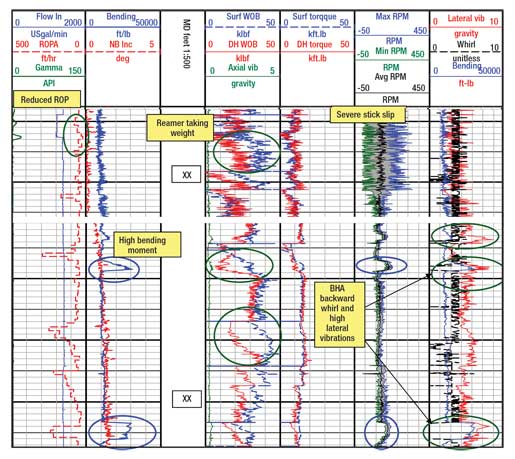 |
Fig. 5. These log excerpts show weight transfer problems. An increase in bending moment, due to backward whirl, is triggered by increases in rotary speed.
|
|
About 300 ft below this point, the bit drilled into an inclusion, and the downhole torque measured by the dynamics tool increased. When the reamer got to the same spot, it reacted to the formation change by taking a lot of weight, slowing ROP. At this point, a strong lateral vibration, BHA whirl, developed. Stopping drillpipe rotation for some time and gradual restarting it did help to overcome the weight transfer problem, however, it failed to eliminate the BHA whirl. It was not until RPM was dropped to 100, while maintaining 40 klb WOB, that a smoother drilling environment was established. The time log documents the onsite engineer’s efforts to improve ROP over the rest of the run by decreasing RPM from 120 to 99 to reduce lateral vibration, Fig. 6.
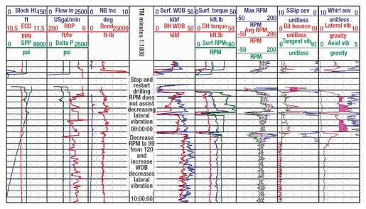 |
Fig. 6. Reductions in surface rotary speed led to a reduction in lateral vibration level. At the same time, WOB is increased to keep the bit on bottom for ROP increase.
|
|
Parameter management to reduce or eliminate drilling dysfunctions was successful due to accurate downhole information and proper drilling team communication. In this well, the rotary speed and the weight had to be controlled within ±20 RPM in some intervals without inclusions, up to ±51 RPM in intervals with inclusions and within ±35 klb WOB adjustments in most cases to mitigate possible catastrophic whirl, lateral and torsional vibration.
The downhole WOB measurement determined the weight taken by the reamer in the drilling process. In the logs, the difference between the surface and downhole weight is the weight taken by the reamer. This insight helped identify situations where the bit was out-drilling the reamer; i.e., the reamer accumulates more weight while establishing its cutting pattern, thus reducing the overall penetration rate, Fig. 7. The diagram shows an almost linear increase in ROP while reducing the RPM at the same time. The high variations show that there was no single solution to effective drilling, as long as environmental factors constantly changed. This emphasizes the need for timely, accurate downhole feedback from the drilling optimization tool.
 |
Fig. 7. As rotary speed is reduced and the reamer net weight is increased, ROP increases.
|
|
WHIRL DIAGNOSTICS AND BENDING MOMENT
When drilling this vertical well with an underreamer, several severe whirl events were observed, especially below the hole-opener. Whirl is caused by off-center rotation with a drillstring mass imbalance. In some cases, forward whirl develops, which causes eccentric component wear as the drillstring rotates clockwise in the direction of bit rotation.
Backward whirl causes excessive cyclic stress reversal, leading to fatigue as the drillstring center moves around the borehole faster than the applied rotary speed. In Figure 5, several attempts to increase RPM resulted in backward whirl, causing the driller to immediately reduce the rotary speed to prevent BHA failure.
The bending moment describes the bending stresses that drillstring components experience. Bending stresses can be from directional changes in the wellbore or from the drillstring’s whirl motion, which causes high, dynamic, bending-stress changes.
CONCLUSIONS
The main achievement was drilling this interval with no twist-off or other catastrophic drillstring failure that would have increased the interval drilling time and probably delayed the entire project. Proper drilling enabled the operator to improve the downhole drilling environment by optimizing drilling.
Downhole weight measurement successfully identified the weight taken by the reamer, which can’t be recognized by the standard WOB measurement at surface. The dynamics tool also confirmed that the reamer was activated, eliminating another hole-opening trip before the casing was run. Loss of stabilization was also seen as a cause of whirl that could have been detrimental to the drillstring.
Real-time updating and intervention by an experienced dedicated onsite engineer were crucial to successfully drill this section. The engineer’s presence helped to establish the required focus for mitigating critical situations.
The experience gained in this vibration-prone zone has been valuable to subsequent BHA designs and the operator’s drilling activities in other planned well sections in this field. The interval was finished nearly vertical, with 2.8° maximum inclination, a dogleg created when the reamer engaged a formation stringer.
The drilling practices established in this section will be used as a standard for this field, where all prior drilling attempts encountered at least one major failure using other equipment. 
ACKNOWLEDGEMENTS
The authors thank Baker Hughes INTEQ for their support and permission to publish this article, and acknowledge the operators involved in the drilling. We acknowledge the contributions of Ricardo Mock, Paul Stoll, Nazaad Baksh, Bud Dailey and Ed Robnett. Finally, we acknowledge the drilling contractors and service companies on this project. This article was prepared from AADE-07-NTCE-11 presented at the 2007 AADE National Technical Conference and Exhibition Houston, Texas, April 10-12, 2007.
LITERATURE CITED
1 Aniekwena A. U., McVay, D. A, Ahr, W. M, and J. S. Watkins, “Integrated characterization of the thin-bedded 8 reservoir, Green Canyon 18, Gulf of Mexico,” SPE 84051 presented at the SPE Annual Technical Conference and Exhibition held in Denver, Colorado, October 5-8, 2003.
2 Lenamond, C., and A. Carvalho, “Fully-rotating rotary steerable and concentric reamers technology combination eliminate wellbore threading in deepwater,” SPE/IADC 91929 presented at SPE/IADC Drilling Conference held in Amsterdam, The Netherlands, February 23-25, 2005.
3 Sheshtawy, A., Sheshtawy, N., Isa, N. and P. Lloyd, “Field experience with advanced design hole opening tools,” AADE-03-NTCE-34 presented at AADE National Technology Conference-Practical solutions for drilling challenges held in Houston, Texas, April 1-3, 2003.
4 Heisig, G., Hood, J., Okewunmi, S., and E. Robnett, “Achieving shoe to shoe drilling performance in hole opening application with rotary steerable systems,” SPE/IADC 105578 presented at the 2007 SPE/IADC Drilling Conference held in Amsterdam, The Netherlands, February 20-22, 2007.
5 Heisig, G., Sancho, J. and J. D. Macpherson, “Downhole diagnosis of drilling dynamics data provides new level drilling process control to driller,” SPE 49206, at the 1998 SPE Annual Technical Conference and Exhibition in New Orleans, Louisiana, Sept 27-30, 1998.
6 Eaton, L. F., McDonald, S., and E. M. Rodriguez, “First simultaneous application of rotary steerable/ream-while-drill on Ursa horizontal well,” SPE/IADC 67760, at SPE/IADC Drilling Conference held in Amsterdam, The Netherlands, February 27-March 1, 2001.
|
THE AUTHORS
|
|
Shola Okewunmi earned degrees in mechanical engineering from Yaba College of Technology and University of Ife, both in Nigeria, and an MBA from University of Houston, Texas. He has 14 years’ industry experience. Okewunmi is presently business development manager for Baker Hughes INTEQ’s CoPilot Drilling Optimization Service for GOM, Trinidad and East Coast Canada.
|
|
| |
Marcus Oesterberg earned an MS degree in mechanical engineering from the Technical University in Clausthal, Germany. He joined Baker Hughes INTEQ in 1995 and has held roles in engineering, marketing and operations. Oesterberg is presently repair and maintenance manager for North America in Houston.
|
|
| |
Gerald Heisig earned a PhD degree in mechanical engineering from the University of Braunschweig in Germany. He has 18 years’ experience in drilling. Heisig is presently application engineering manager in Baker Hughes INTEQ for the Middle East and Asia Pacific.
|
|
| |
James Hood earned a BS in geology from Bowling Green State University, Ohio. He has spent most of his 25+-yr international oil industry career advising on drilling optimization. Hood is presently drilling optimization advisor for North America for Baker Hughes INTEQ.
|
|
|


