SPECIAL FOCUS: OFFSHORE REPORT
Short-order redesign of an intelligent control completion offshore Nigeria
The Okwori subsea development combining expandable sand screens and intelligent control overcame failure of a key component to make its first-oil deadline.
Jim Stevenson, Total E&P Angola; Rodger Lacy, Juergen Neumann and Gary Tough, Weatherford
Since Okwori field was discovered offshore Nigeria in 1972, several successive lease holders studied the possibility of development, but the field’s geological complexity made development too difficult to be considered economic. It was not until Addax Petroleum Nigeria Ltd. acquired the lease in 1998 that a serious attempt was made to exploit the field’s potential. A development plan was put together and was approved by the Nigerian regulators in 2002.
To develop the field economically and address the difficulties it posed, it was decided to use a series of subsea wells, each completed in multiple zones and tied back to an FPSO. The wells were to be completed using a combination of expandable sand screens and remotely operated intelligent completion flow valves. Due to the complexity of the completion, Addax chose to use a single contractor to supply all the components. When the initial completion was attempted, a vital piece of downhole equipment - which was key to the intelligent completion’s operation - failed, precipitating a re-conceptualization of the completion. In very short order and under extreme time constraints, an alternative approach was designed using the same subsea equipment, and the first four completions were made successfully within the timetable dictated by Addax production commitments.
BACKGROUND
Addax Petroleum Development Ltd. acquired Okwori field in 1998. It is located in oil mining lease OML 126 offshore Nigeria, south of Port Harcourt, in water depths of 165 - 690 ft (50 - 210 m). Okwori field is extremely complex geologically, with a large number of reservoir layers and faulted compartments containing numerous pools with hydrocarbon-bearing potential. The occurrence of a collapsed-crest anticline along two intersecting sets of syn- and post-sedimentary fault planes explains the structural complexity indicated in two 3D seismic surveys that mapped more than 100 fault-dip closures. Before Addax began field development, six wells were drilled in the field and penetrated 30 of these pools. The oil-water contacts were found to be highly variable among the reservoirs and also among compartments of the same reservoir.1 Adding to the complexity of field development, the oil-bearing sands are all weakly to fairly consolidated sandstones and very permeable; thus, adequate sand control is essential to successful production from the reservoirs.2
The field’s highly faulted and compartmentalized reservoirs required dispersed well locations. Addax developed a master field-development plan that called for a series of subsea wells each tied back to a central FPSO, Fig. 1. Initially the plan advocated the use of four existing wells that had been drilled, tested and suspended by a previous operator. However, after risk evaluation of the wells by the Addax well engineering team, the decision was made to drill and complete eight new wells instead. The cost of developing the field in this manner, using a semisubmersible rig to drill and complete the wells, required that each well have high production capacity. Thus, each well needed to produce from several of the oil-bearing reservoirs. Commingled flow from each well would be the simplest and quickest design, but host country regulations dictated that independent control be maintained over each producing zone to facilitate allocation of production by zone. Once the master field-development plan was initiated and the drilling commenced, there would be a scheduled timeline to the FPSO’s arrival and the production of first oil from the field, with financial penalties for delays.
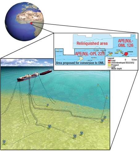 |
Fig. 1. The layout of the FPSO deployment in the Okwori field area.
|
|
The Addax well engineering team decided early in the preparation of the master field-development program to use hydraulic, remotely operated sliding sleeves to control each producing interval independently. The completion was designed to enable production of a single reservoir or any combination of reservoirs in commingled production, thereby limiting the need for subsequent interventions with a semisubmersible rig at very high operational cost.3 Another requirement was that the sliding sleeves be compatible with the sand control method chosen.
COMPLETION DESIGN
The well engineering team examined the sand control technology available and determined that Expandable Sand Screens (ESS) deployed inside 9 5/8-in. casing would provide the inside diameter required to install an inner string with Remotely Operated Sliding Sleeves (ROSSs) and zonal isolation packers. The requirement of high productivity and maximum ID through the sand control medium eliminated the possibility of cased-hole gravel pack.
Initially, two completion designs (to suit 9 5/8-in. casing to TD or a 7-in. liner) had been selected for the existing suspended wells. However, after the decision was made not to re-enter the suspended wells, the Addax well engineering team, in conjunction with a peer review team, opted to drill all new wells and run 9 5/8-in. casing to TD. The 7-in. liner design was retained as a contingency in case any wells encountered difficulties during drilling.
A 9 5/8-in. production casing string would be cemented across the producing zones and perforated. Then a 7 5/8-in. outer string would be spaced inside the cemented 95/8-in. production casing to place Expandable Sand Screens (ESSs) across the perforated producing intervals, with 9 5/8-in. isolation packers set between the producing intervals to provide zonal isolation. The inner string would consist of a number of hydraulic ROSSs mounted on 3½-in. production tubing, separated by 7 5/8-in. x 3 ½-in. production packers with hydraulic control-line feed-through capabilities set in the 7 5/8-in. blank pipe to provide zonal isolation. Above the expandable sand-screen liner hanger, a 9 5/8-in. production packer would be set with hydraulic control-line feed-through capability. In accordance with accepted subsea practices and HSE standards, this production packer would require intervention to release.
One of the keys to the proposed completion design was the use of a single hydraulically controlled addressing (or indexing) unit, which can independently control up to four ROSSs using only two control lines to surface. Applied pressure down the control lines activates the addressing unit, and applying pressure in a systematic pattern causes the unit to index from position 1 to position 2, to position 3 and so on. When the unit is at a specific position, the ROSS valve corresponding to that position can be opened or closed.
Under normal circumstances, each ROSS requires two control lines - one to open and one to close - so a total of eight control lines would be required to independently operate each one. This would require eight feed-through points at the wellhead and eight lines in the umbilical to the FPSO, making it a complex and costly installation. However, incorporating an indexing unit would reduce the number of control lines needed to two.
The indexing unit was to be mounted in the 3½-in. production tubing below the 95/8-in. top production packer, above which the tubing would be crossed over to a 4½-in. production string with 4½-in. gas-lift side-pocket mandrels to a 4½-in. surface-controlled subsurface safety valve to complete the production string, Fig. 2.
 |
Fig. 2. General completion schematic for Okwori development wells.
|
|
PROJECT MANAGEMENT
Recognizing the necessity of an interface with the supplier and of continuity in management of the complex completion system’s manufacture, shipping, assembly, testing and final installation, the Addax well engineering team recommended that a single service provider supply the entire completion system. This strategy was intended to create a cooperative union between the operator and the service company providing the equipment and installation expertise, leading to a seamless project management organization. The service company selected, Weatherford, was called upon to provide detailed completion designs for installing the ESSs to address the sand control issues and for the inner production string of ROSSs, feed-through packers, control lines and additional equipment. As part of this project management, Weatherford would also provide schedules of manufacturing, final assurance tests, assembly and shipping to Nigeria, and preparation for installation in the wells to meet Addax’s project schedule and first-oil deadlines.
Weatherford assigned two project engineers to the program, one for the outer string (including ESSs and packers) and one for the inner string (including downhole control valves, packers and the indexing unit). These project engineers would coordinate with Weatherford’s engineering design, manufacturing, QHSE and operational units and with the Addax well completion engineer based in Lagos, Nigeria. The various components of the completion were being manufactured at plants in Houston, Texas; Huntsville, Texas; Lafayette, Louisiana; Edmonton, Alberta; and Aberdeen, Scotland. Weekly conference calls were set up to ensure that Weatherford personnel responsible for any part of the project were regularly informed of progress by their counterparts. Each project engineer summarized these weekly conference calls and reported progress to the Addax completion engineer according to the critical path analysis.
When the manufacturing plants completed the components required for the first four wells, these components were shipped to a staging warehouse in Lafayette, Louisiana, where assembly and stack-up testing were to be performed. The project engineers and a team of operational personnel were gathered in Lafayette along with the Addax completion engineer, and the equipment was inspected, assembled and tested. The equipment was then meticulously identified with part and assembly number cross-referenced to specific wells, crated and shipped to Nigeria.
Upon arrival at the Weatherford base in Nigeria, the equipment was uncrated and assembled for a final test before loadout. All components were fully function-tested and loaded into offshore baskets for transport to the rig in pre-made-up assemblies.
INITIAL COMPLETION ATTEMPT
The first Okwori well was drilled, and 9 5/8-in. production casing was cemented. The casing was then displaced to clean filtered brine, and three separate intervals were perforated with big-hole, high - shot-density, tubing-conveyed perforating guns. Once losses were cured with lost-circulation-material pills, the ESSs were picked up and run into the well. A detailed well schematic and running plan ensured correct spacing of the ESSs across the perforated intervals and of the two 9 5/8-in. isolation packers in the blank pipe between producing intervals. The liner hanger carrying the 5½-in. ESSs and 7 5/8-in. blank pipe was set, and the running tool was released. Then the ESSs were compliantly expanded, the expansion tool was pulled out of the hole, and the straddle tool was picked up and run in. The straddle tool had two packers spaced out such that each packer would set in the blank pipe just above one of the 9 5/8-in. isolation packers. Once the straddle tool was set in place, pressure applied to the drill pipe set the isolation packers, and the straddle tool was pulled from the well.
The inner string consisting of the 3½-in. ROSS downhole flow-control valves, 7 5/8-in. control-line feed-through packers, the hydraulically controlled addressing unit and the top 9 5/8-in. feed-through production packer was picked up and run in the well. At setting depth, the addressing unit was pressured up but did not respond as designed, indicating a leak, so the decision was made to pull out of the hole and run the backup equipment.
The backup inner string system was then run in the well, with an operational test of the addressing unit conducted every 1,000 ft. At 5,000 ft, the unit failed again and began leaking. The equipment was pulled out of the hole, and the operation was suspended pending a decision by Addax.
CORRECTIVE MEASURES
In a conference call between the Weatherford engineering and operations personnel and the Okwori project’s Addax management, the decision was made to suspend the completion, move the rig to the next wellsite and commence drilling. This would give the staff additional time to assess the problem and come up with a viable solution. The Weatherford engineering department needed to examine the two addressing units that had failed while running in the well, and evaluate the data to make a recommendation. Addax’s decision to move the rig to the next well was a gamble on Weatherford’s ability to find a solution within the 30 days it would take to drill the second well, so that the project could meet its first-oil date.
Examination of the addressing unit revealed a design weakness that had not been detected during either the initial prototype testing or the final assurance testing. The hydraulic fluid was supposed to be filtered to US National Aerospace Standard, Class 6. Filtering of hydraulic fluid recovered from the failed units revealed foreign matter, in the form of very fine shavings of steel. The recommendation was to design and build a filter sub to capture any foreign material and return the hydraulic fluid to NAS6 standard. This design was undertaken in the short time available, and a filter sub was made available, in case Addax management decided to use it, Fig. 3. The filter sub had an individual filter and sump for each control line. Control-line fluid would flow into the sumps to retain most of the debris before reaching the filters. This would avoid plugging and prevent any foreign material from reaching the operating components.
 |
Fig. 3. Specially designed filter sub.
|
|
Weatherford advised that this design change should eliminate the problem, but in case the operator demanded a more substantial change, the staff also designed an alternate configuration that would eliminate the hydraulic controller. In the revised configuration, one additional control line would be required and the hydraulically controlled addressing unit would be replaced with pressure-relief “crack” valves, Fig. 4. The pressure-relief valve would be placed above one or two of the ROSS valves, depending on the number of zones. When control-line pressure was maintained below a predefined threshold, the ROSS valve below the pressure-relief sub would remain undisturbed while the pressure activated other ROSSs. As pressure was increased to exceed the predefined value, an internal valve would open (“crack”), allowing pressure to operate the remaining ROSS.
 |
Fig. 4. Pressure relief valve sub.
|
|
The third control line was already in the existing umbilical and in the control-line flatpack because early design stages had included a chemical injection line. This line could be used as the third control line and could be readily accommodated by modifying the tubing hanger to accept an additional penetration. Three control lines would give completely independent control over two ROSS valves, while three or four ROSS valves could be operated similarly, but with a slightly more complex logic, Fig. 5. To open just the ROSS valve below the pressure-relief sub, high pressure would be applied through one control line to open both the upper and lower valves, and then low pressure through another line would close only the upper valve. All that was needed was an additional control panel on the FPSO and a modification to the control software.
 |
Fig. 5. Two-, three- and four-zone well architectures.
|
|
After considering the alternatives, Addax project management determined the risk too great to try a design change in the failed hydraulic addressing unit, and decided to use the three-control-line system.
THREE-CONTROL-LINE SYSTEM
Each ROSS has two hydraulic connection points, one to close the valve and one to open it. The ROSSs are designated ROSS-1, ROSS-2 and so on from the bottom unit up.
The logic to operate the two-, three- and four-zone completion configurations is based on a “telltale” position before moving to any valve configuration; “telltale” is defined as the position where all valves are closed and the well can be opened with no flow resulting. From this known point, a selected valve can be opened by application of the appropriate pressure. The pressures required to operate the system are defined as follows:
- Low Pressure (LP) = 3,000 psi
- High Pressure (HP) = 5,000 psi
- High High Pressure (HHP)* = 7,500 psi.
By applying LP or HP pressures in sequence to a selected line or lines in the prescribed sequence, each valve can be independently opened or closed. The sequence of pressure applications required depends on the number of ROSSs in the completion. For example, Fig. 6 shows the sequences for either commingled or selective flow in a three-zone well. Similar sequential operations apply to two- and four-zone wells.
  |
Fig. 6. The operational sequences for selective flow (left) and commingled flow (right) in a three-zone well.
|
|
INSTALLATION
The first three-control-line system was run and installed on the second Okwori well. This well was a three-zone installation which, with the new software installed in the control panel on the FPSO, allowed control over each of the ROSS valves. Since then, four more wells have been drilled and completed as three-zone installations with ESS outer strings and inner strings with hydraulic ROSSs. In addition, two Okwori wells have been completed as four-zone installations; another Okwori well and stepout well in the nearby Nda asset have been completed as two-zone-producing wells using the same basic completion system. First oil was produced in March 2005, and in March 2006 the field was producing about 27,000 bopd.
CONCLUSIONS
This project represents the first completion of a subsea well with expandable sand screens and intelligent completion systems. The problems that occurred during the first completion attempt led to the following conclusions:
- The provision of three control lines from surface can independently control up to four downhole remotely operated sliding sleeves
- By working together and eliminating the culture of blame and “finger pointing” prevalent in some operator/service company relationships, difficult situations can be solved to the benefit of both parties.
These lessons may be useful for future projects. 
* The HHP pressure is only used as an alternative should the valves fail to move with either LP or HP application, and will require modification to the control panel.
ACKNOWLEDGEMENTS
This article was prepared from OTC 18484 presented at the Offshore Technology Conference held in Houston, April 30 - May 3, 2007. The authors thank Addax Petroleum Nigeria Ltd. for permission to publish this paper.
LITERATURE CITED
1 Guinot, F. et al., “Optimization of well performance in a selective subsea sand-control completion, offshore Nigeria,” SPE 98226 presented at the SPE International Symposium and Exhibition, Lafayette, La., USA, Feb. 15 - 17, 2006.
2 Clark R.A. et al., “Case study: Redevelopment of the Ebughu field,” SPE 65199 presented at the SPE European Petroleum Conference, Paris, Oct. 24 - 25, 2000.
3 Jan Saeby et al., “The use of expandable sand-control technology as a step change for multiple-zone SMART well completion: A case study,” SPE 68634 presented at the SPE Asia Pacific Oil and Gas Conference and Exhibition, Jakarta, April 17 - 19, 2001.
|
THE AUTHORS
|
|
Jim Stevenson is a consultant on a deepwater field development for Total E&P Angola. He was engaged by Addax to perform a subsea completion role during the Okwori completions project. He began his career with Camco in 1976 and has subsequently worked as a subsea completion engineer, product line manager and consultant for major operating and service companies.
|
|
| |
Rodger Lacy is an account manager for Weatherford. Now based in The Hague, he served as Weatherford’s country manager of Nigeria from April 2003 to May 2006. Mr. Lacy began his career in 1978 with Baker Packers. He has worked as a field engineer, district manager, regional manager and country manager. Mr. Lacy is a member of SPE and has published numerous technical articles.
|
|
| |
Juergen Neumann is business development manager for Weatherford Nigeria based in Lagos. With over 18 years’ experience in the oil industry, Mr. Neumann has held positions in operations, technical management, sales, marketing and line management with major service companies. He holds a degree in mining engineering from the University of Aachen, Germany, and is a member of SPE.
|
|
| |
Gary Tough is project and operations manager of production optimization for Weatherford, based in Aberdeen. He has been with Weatherford since 2002. He began his career in 1997 with Expro North Sea and has served as a field service engineer, project engineer and project manager. Mr. Tough holds an electrical and electronic engineering degree from Robert Gordon University.
|
|


