TECHNOLOGY
Intelligent multilateral MRC wells drilled and completed in Haradh Inc-3
Intelligently completed MRC wells have improved Aramco’s development economics.
Fahad Al-Bani and Ahmad Shah Baim, Saudi Aramco; and Suresh Jacob, WellDynamics Inc.
The Haradh Increment-3 (HRDH Inc-3) development, commissioned in March 2006, has added significant volumes to Saudi Aramco’s daily productive capacity. The development has 73 wells, including 28 water injectors, 13 observation wells and 32 producers. Twenty-eight producers are intelligent completions in multilateral wells.
Maximum Reservoir Contact (MRC) wells with multilateral systems improve reservoir contact while reducing reservoir drawdown. The intelligent well system (IWS) allows inflow from each lateral to be controlled from the surface without well intervention. This combination should enhance field recovery by preventing/delaying water coning and improving sweep efficiency.
Application of cutting-edge technologies, like rotary steerable system (RSS), real-time drilling data transmission, geosteering, non-damaging fluids, multilateral systems and intelligent completions, has helped to achieve maximum, effective reservoir contact and deliver wells ahead of schedule. Producers were drilled with three or four laterals, depending on well location. Each lateral has about 4,000 ft of reservoir contact. The average reservoir contact for each well is over 14,000 ft.
The wells are constructed as Technology Advancement in Multi-Lateral (TAML) Level-2 systems, where openhole laterals are drilled out of the motherbore that is cased and cemented. This article describes field planning, drilling and completion practices, as well as challenges faced in drilling and completing these complex multilateral MRC wells within a tight schedule.
BACKGROUND
HRDH Inc-3 is the southernmost part of greater Ghawar field, Fig. 1.
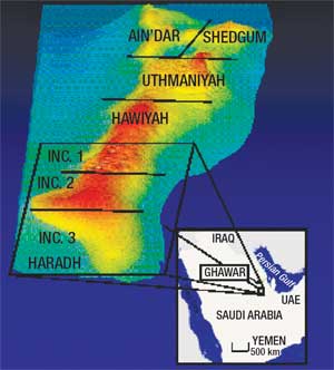 |
Fig. 1. Ghawar field, highlighting the Haradh area and boundaries.
|
|
Initial developments at Haradh Inc-1 used conventional vertical wells, and Haradh Inc-2 was developed with long horizontal wells. Advancements in technology have enabled HRDH Inc-3 to be developed with MRC wells and SmartWells™. Studies have shown that multilateral MRC wells with intelligent completions will have prolonged life, reduce the decline rate and minimize water handling. Smart laterals are a combination of IWS completions in conjunction with multilateral wells, Fig. 2. The IWS includes surface-controlled downhole control choke, isolation packers and pressure/temperature sensors placed in the motherbore. This system enables remote control inflow from each lateral.
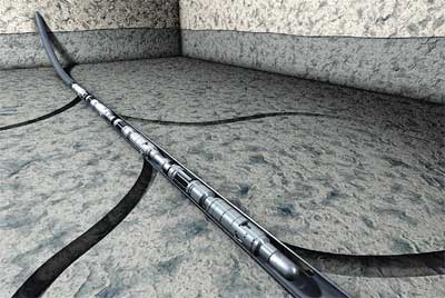 |
Fig. 2. Illustration of an intelligent completion inside a multilateral well.
|
|
Drilling and completion of wells were preceded by a full-field evaluation, consisting of fluid flow behavior, displacement mechanism, sweep efficiency and well performance modeling.1 Water production on a field basis was reduced, compared to cases without IWS’s.
A formation damage and wellbore clean-up team was created to review the drilling fluid, and provide a drill-in fluid design and set of fluid parameters to maintain while drilling each lateral.2 A team of drilling engineers, reservoir engineers, geologists and petrophysicists was created to enhance geosteering and streamline decision-making at the 24/7 Geosteering Operations Center (GOC). Development began in February 2005 with 28 water injection wells at the field’s periphery. Thirteen observation wells were drilled and completed with permanent downhole gauges to monitor fluid front movement in the reservoir. The first producer was drilled in October 2005.
WELL PLANNING
Producer wells were planned with 28-in., 22-in. and 16-in. upper vertical sections. The 12 ¼-in. section was planned to be directionally drilled to the top of the reservoir with geosteering, motor on PDC bit. The 8½-in. hole was planned with geosteering to the top of the 7-in. liner point. This was to be drilled in a horizontal section, with dog leg severity (DLS) less than 4°/100 ft to reduce the drag while running the 7-in. liner and completion. The windows were cut in the hole’s upper side to avoid the completion string hanging up at the windows. The 6 1/8-in. openhole laterals were to be drilled out of the 7-in. liner. Total reservoir contact per well was over 5 km. A 300-m separation was kept between laterals for efficient drainage.
HRDH Inc-3 can be considered the first field development based on multilateral wells and intelligent completions. TAML Level-2 multilateral systems with cased and cemented motherbore and openhole laterals were selected, due to the presence of consolidated rock at junction points. The all-hydraulic IWS was selected because of its higher reliability and track record. At the peak of development, 16 rigs were running in HRDH Inc-3, and it was important that procedures and equipment were consistent, and that lessons learned were quickly transferred to other units.
DRILLING OPERATIONS
Figure 3 shows the well/casing plan for an MRC well in HRDH Inc-3. The well’s upper sections (28-in. to 16-in.) were drilled with spud mud.
 |
Fig. 3. Casing plan and well trajectory for mulltilateral well.
|
|
The 12¼-in. section was drilled with light mud to improve lubricity and sliding efficiency prior to entering the non-targeted upper reservoir.3 In cases where this upper reservoir was flowing, mud weight was increased, and drilling continued to the top of the targeted reservoir. Different motor/PDC bit combinations were tried to optimize rate of penetration (ROP). The 8½-in. hole section was drilled and geosteered with RSS. This section was cased and cemented with 7-in. liner, and it was the motherbore for the laterals. Based on recommendations of the geosteering team, the 8½-in. section was drilled as a smooth, straight hole close to the top of the structure.
The TAML Level-2 multilateral windows were set at 300-m separation, based on reservoir studies and evaluation of inter-lateral interference. The hydraulically-set whipstock with packer was run in conjunction with the tri-mill and MWD assembly. The whipstock was run, oriented to the upper quadrant, and the window milled in one trip. The 6 1/8-in. openhole lateral’s initial section was drilled with a motor and changed to RSS as friction increased. The 6 1/8-in. openhole sections are the well’s producing zones. Deep-imaging LWD tools were used to optimize well placement and collect data to update reservoir models. Length and direction of laterals were optimized for better recovery.
INTELLIGENT LATERALS
Intelligent completions and multilateral wells have enabled operators to improve and optimize reservoir development processes, increase reservoir contact and improve sweep efficiency at lower drilling costs. Intelligent completions enable operators to monitor and control inflow at the reservoir, remotely without well intervention, and help optimize wells in real time. Improvements in the reliability and track record of these individual technologies have enabled these systems to be combined, leading to incremental benefits. Intelligent wells in multilaterals were successfully installed by Saudi Aramco in March 2004. After that, over 55 intelligent wells were installed throughout Saudi Aramco, as of early 2007.
The IWS’s consist of hydraulically operated, surface-controlled downhole chokes, each with 10 discrete positions. Choke sizes were designed to meet the flowrate during the life of the well. The downhole control valve is positioned using the AccuPulse™ choke system that dispenses a fixed volume of fluid in each pressure cycle and opens the choke by one position. This can close the choke from any position in one pressure cycle.
Hydraulically-set, retrievable packers were used to provide isolation between the laterals, These packers have control line ports with isolation fitting to pass the control lines. A combination of Inconel 718 and AISI 4140 metallurgy was used to meet well conditions. The completion consists of 3½-in. tools for the lower laterals and 5½-in. tools for the upper lateral. For 6,000 ft in the top section, 7-in. tubing was used to allow future ESP installation and retrieval without affecting the IWS completion.
COMPLETION DESIGN
Production strings consisted of IWS equipment run in the motherbore, from top to bottom as follows:
- Tubing hanger
- Two control line flatpacks (one for IWS and one for downhole gauges)
- 7-in. production tubing
- 5½-in. tubing
- 5½-in. deep-set surface-controlled subsurface safety valve (SCSSV)
- Sliding side door (SSD)
- IWS assembly for upper lateral
- Prod. tubing to next lower lateral
- IWS assembly for middle lateral
- Prod. tubing to next lower lateral
- IWS assembly for lower lateral
- Production tubing to motherbore
- IWS assembly for motherbore.
IWS ASSEMBLY
The IWS assembly for each lateral was 43 ft long and consisted of the following (from top to bottom):
- Upper splice sub
- Retrievable, hydraulically-set production packer, with control line and Tubing-Encapsulated Conductor (TEC) pass-through ports
- Interval Control Valve (ICV) for the upper interval
- Lower splice sub (or bull nose in the lower-most assembly).
The IVC is a 10-position, hydraulically-operated, surface-controlled downhole choke. Production from each zone enters the tubing through the ICV.4 It uses a tungsten carbide choke with a metal-to-metal sealing surface that is rated to 7,500 psi differential in either direction. Each ICV contains a locking mechanism to lock the choke on close position and prevent inadvertent functioning, due to downhole conditions. In case of any damage to the hydraulic control lines, the ICVs are “fail as-is.” The seals isolating the control line pressure from the tubing or annulus pressure are rated to 10,000 psi. As a backup to the hydraulic system, the ICV has a built-in shifting profile to allow it to be shifted using coiled tubing or slickline.
The choke is mounted on a hydraulically-operated sleeve and provides full-bore ID at all times. This enables lower zones to continue producing through tubing, even when an upper ICV is closed. The lower ICV controls flow from the motherbore, and the packer provides isolation from the upper lateral(s). Flow from the upper lateral(s) enters the mainbore at the junction, follows an annular flowpath behind tubing, and enters production tubing at the ICV for that zone.
The ICVs are operated by a direct hydraulic system with AccuPulse choking, where hydraulic force is applied on either side of a piston at the ICV to move the valve to the “open” or “closed” position. In the “open” line, the fluid passes through the Accupulse, which displaces a fixed amount of fluid to the valve, causing it to move a predetermined distance and open to the next choke position. This incremental displacement is repeated to achieve the intermediate choke positions.
In Haradh Inc-3, the system was configured to incrementally open from closed to fully open through nine intermediate positions. This allows the choke to be fully closed from any open position by applying pressure in the closed line only once. The ability to close immediately from any intermediate position is useful in well control and high water cut applications.
The hydraulic system is closed, where the fluid volume pumped down to function a valve is returned to the surface hydraulic panel through the remaining control line. Hydraulic control fluid is never vented to the production tubing. About 15 in.2 of fluid can move the ICV from fully closed to fully open, or vice-versa.
Once the automated surface panels and control module were installed, the system would supply hydraulic fluid at 4,000 psi to operate the ICVs. With 4,000 psi of control-line pressure, the piston generates over 12,000 lb/ft in either direction while opening or closing the valves. This is much greater than the force that can be generated by slickline or coiled tubing. The control system will enable gauges and valves to be monitored and operated remotely from the control room through a field SCADA system.
REVIEW OF INSTALLATION
Following retrieval of the whipstock, a pre-completion mechanical clean-up trip with magnets, string mills, casing scrapers and junk baskets was conducted in the mainbore. The well was displaced to filtered brine. Hi-vis/low-vis sweeps were pumped to lift the cuttings. The window edges were dressed with the string mills to remove any ledges that could stop the completion from passing through. The drag on the clean-up string while passing windows was recorded to ensure that the string was still in the mainbore and did not enter the lateral. Finally, the string was run past the windows without rotating to simulate the completion string. The debris collected in the junk baskets and magnets were analyzed to ensure that the well was sufficiently cleaned for trouble-free IWS installation.
The IWS assembly for the mainbore was picked up, and control lines made up the splice sub. The ICV and the control lines were tested. About 450 ft of tubing were run until the next assembly. The flatpack was anchored to every coupling with cross-coupling clamps. The assembly for the next lateral was made up. Control lines from the lower assembly were connected to the lower splice sub manifold, and control lines from surface were connected to the upper splice sub. The middle IWS assembly and the lower zone were functioned to test line and tool integrity.
Production tubing was run to the next assembly. The IWS for the upper lateral was made up, control lines were connected, and all three valves were function-tested. The sliding side door (SSD) was made up above the upper packer. The SSD is used to displace the upper annulus with diesel after setting the packer. The single-point pressure/temperature gauge is made up above the SSD. Production tubing was run to surface with the hydraulic and I-wire anchored at every joint with the cross coupling clamps. At surface, the tubing hanger was made up, plastic stripped from the control lines, and bare control lines were fed through the ports on the tubing hanger. Isolation fittings were installed on control line ports, and the tubing hanger was landed. Downhole valves were functioned and the tubing pressured to 4,300 psi to set the packers.
Throughout completion, the ICVs shifted on command and held all differential pressures imposed upon them. The ICVs were successfully pressure-tested up to six times during completion. They accurately recorded pressure and temperature from all three locations with no data errors logged.
BEST PRACTICES AND LESSONS
The sharing of best practices and lessons enabled drilling time to be reduced from 88 days for initial wells, to an average 60 days toward project’s end. One MRC multilateral well was drilled and completed in 47 days. Lessons learned and best practices were recorded on the Aramco E&P Continuing Excellence program intranet website. One of the crucial factors that reduced rig time was the improvement in ROP. The ROP for 8½-in. and 6 1/8-in. sections was improved 50% and 80%, respectively.
PRODUCTION OPERATIONS
All the wells in Haradh Inc-3 are producing, and the IWS’s are functional. The permanent downhole gauges provide real-time data on well and reservoir conditions, and the generated data are used for production and reservoir management decisions on an ongoing basis.
The intelligent completions at HRDH Inc-3 provide the operator with a high level of flexibility in producing the wells. For example, laterals may be individually produced until the reservoir pressures enable commingling without cross-flow. Laterals with high water or gas may be choked back, and other suitable zones are opened to compensate. IWS configurations also enable the operator to quickly respond to reservoir uncertainties. 
ACKNOWLEDGEMENT
The authors would like to thank Saudi Aramco and WellDynamics Inc. for their support and permission to publish this work.
This article is derived from SPEIADC paper 105715, presented at the IADC/SPE Drilling Conference, Amsterdam, The Netherlands, Feb. 20-22, 2007.
REFERENCES
1 N. I. Afaleg, et al, “Design and development of maximum reservoir contact wells with smart completions in the development of a carbonate reservoir,” SPE paper 93138, presented at the SPE Asia Pacific Oil and Gas Conference and Exhibition, Jakarta, Indonesia, April 5-7, 2005.
2 D. Hembling, et al, “Drill-in fluids for MRC wells in HRDH Inc-3,” Saudi Aramco report, May 4, 2005.
3 F. A. Al-Bani, et al, “Drilling and completion program for Harad Inc-3 wells,” Saudi Aramco procedure, November 2005.
4 S. Jacob, et al, “Completion guidelines for Smartwell completions,” Saudi Aramco-WellDynamics procedure, April 2006.
5 C. D. Stair, et al, “Na Kika intelligent wells-Design and construction,” SPE paper 90215, presented at the SPE Annual Technical Conference and Exhibition, Houston, Sept. 26-29, 2004.
6 P. Murray, et al, “Haradh Increment-3-Lessons learned and best practices,” http://eway.aramco.com.sa, Saudi Aramco E&P Continuing Excellence Program, March 2006.
|
THE AUTHORS
|
|
Fahad Al-Bani works in the Drilling Engineering Department, Development Drilling Engineering Division of Saudi Aramco. In 1996, he earned a BS degree in petroleum engineering from King Saud University, Riyadh, Saudi Arabia. He then joined Saudi Aramco as a drilling engineer. In 2005, he held the position of drilling engineering supervisor for HRDH Inc-III. He has been a member of SPE since 1998. .
|
|
 |
Ahmad Shah Baim is a senior drilling engineer for Saudi Aramco and was fully involved in the execution of the Haradh Inc-III Drilling Program. Mr. Baim joined Saudi Aramco in 2005 and has 17 years of experience in the oil and gas industry. He obtained his BS degree in mechanical engineering from Gannon University, Erie, PA, USA, in 1988. He is also a member of SPE.
|
|
 |
Suresh Jacob is the country manager for WellDynamics in Saudi Arabia, responsible for technical and commercial support for the firm�s activity in the kingdom. He has over 10 years of experience in well completion and has worked on several projects encompassing the planning, installation and operation of intelligent well completions..
|
|


