An application of a multilateral junction system offshore Australia’s Northwest Shelf replaces 18 single wells with nine multilateral wells, saving significant time and cost.
Brett Lawrence, Apache Energy Ltd.; Mike Zimmerman, Andy Cuthbert and Steven Fipke, Halliburton
Multilateral technology uses fewer production well slots to effectively drain a reservoir, saving time, money and improving NPV. One of the benefits of multilateral (MLT) well architecture is the reduced cost of the subsea infrastructure. Additional cost benefits include reduced top-hole drilling costs, reduced project execution time, accelerated production, fewer rig moves and a smaller environmental footprint. To take advantage of the benefits, the appropriate multilateral technology must be selected to avoid introducing additional risk and non-productive time (NPT) to the project.
Over the past 10 years, TAML level 5 MLT technology has been used extensively in the North Sea. It had, however, never been used in the southern hemisphere. Because the TAML level 5 system had a proven track record in subsea installations and was able to provide hydraulic and mechanical isolation of connected wellbores, it was decided that the technology would be inaugurated in the Van Gogh field in the Northwest Shelf of Australia.
CHALLENGES OF THE VAN GOGH FIELD
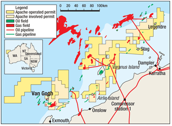
The Van Gogh Field is located about 750 mi northwest of Perth, Australia on the Northwest Shelf of Western Australia, Fig. 1. The water depth on location is about 1,300 ft, and the reservoir formation, the Barrow Group Sandstone, is unconsolidated and friable in nature. The formation is normally pressured, with high porosities and permeabilities. The oil is heavy and fluid properties have slightly corrosive attributes; consequently, all flow-wet areas must be completed with chrome metalurgy components. The oil column is relatively thin and varies in vertical thickness. To obtain adequate drainage, many horizontal oil production legs are required throughout the field, ranging in length from approximately 0.8 to 1.4 mi to maximize exposure.
 |
|
Fig. 1. Relative location of Northwest Shelf of Western Australia..
|
|
Due to its remote and environmentally sensitive location, the Van Gogh field was developed with special consideration of logistics, efficiency and environmental effect. The plan was to develop the field almost entirely with multilateral wells in order to achieve a lower capital expenditure, a shorter project execution time and maximized reservoir coverage.
MULTILATERAL WELL DESIGN
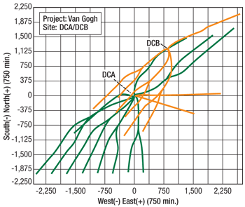
Apache Energy Ltd. contracted two semi-submersible rigs to drill the Van Gogh subsea development simultaneously from two separate drill centers. The Stena Clyde worked from drill center A, and the Ocean Epoch was positioned about 1 mi away at drill center B, Fig. 2. The use of multilateral wells enabled the entire Van Gogh Field to be developed from these two drill centers. Nine dual laterals, one single lateral, two water injectors and one gas injector were drilled from the two subsea surface locations, which maximized the reservoir contact with minimal effect on the seabed.
 |
|
Fig. 2. Van Gogh well paths and relative locations of drill centers A and B.
|
|
The wells were constructed with 30-in. surface casing, a 133/8-in. intermediate casing string and 9 5/8-in. casing in the build section. The horizontal sections were completed with 5½-in. premium sand screens with swellable intelligent packers and helical inflow control devices (ICDs) to optimize the pressure drawdown. Finally, the wells were completed with 5 1/2-in. production tubing to the subsea wellhead. The surface casing and intermediate sections were drilled and completed in batch operations before entering the reservoir to improve efficiency and to reduce the time and costs involved with changing mud systems for the reservoir sections of each well.
The 12 1/4-in. hole sections were drilled using rotary steerable systems, building from 0° to 90° while maintaining a build rate of approximately 3°/10 ft. The 12 1/4-in. section was completed with a 9 5/8-in. casing string with an MLT pre-milled aluminum-wrapped window joint, which was oriented before the final landing; the casing was turned so that the pre-milled casing window was oriented to the high side of the wellbore. To facilitate this, a smooth wellbore with minimal localized dogleg severity was required.
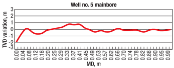
After batch drilling all 12 1/4-in. sections, the horizontal 8 1/2-in. sections were also batch drilled and completed in the reservoir. It was necessary when drilling to maintain tight ±<1 m true vertical depth (TVD) control not only for optimum placement within the reservoir, but also to ensure drag effects were mimimized during deployment of the completion equipment (Fig. 3). Horizontal sections of between 800 and 1,450 ft in length were drilled with a MD:TVD ratio often exceeding 3:1. As with the build sections, rotary steerable drilling systems were used in the horizontal section to maintain tight drilling control and maximize the rate of penetration (ROP). Advanced measurement-while-drilling/logging-while-drilling (MWD/LWD) tools and telemetry systems were used to monitor the position of the well and to record geophysical data.1
 |
|
Fig. 3. Example of tight TVD control of multilateral branch.
|
|
The 8 1/2-in. lateral sections were completed using premium sand-screens on 5½-in. base pipe and slide-on annular swellable packers to compartmentalize the reservoir section. To prevent damage to the filter cake in the reservoir, the screens were run in water-based drilling fluid. Before setting the sand screen completions in place, the reservoir annulus was exchanged to the completion fluid, using an inner string that sealed above a float in the shoe of the completion. This was the first time that an inner string was run inside of the MLT junction with the vendor’s TAML level 5 solution.
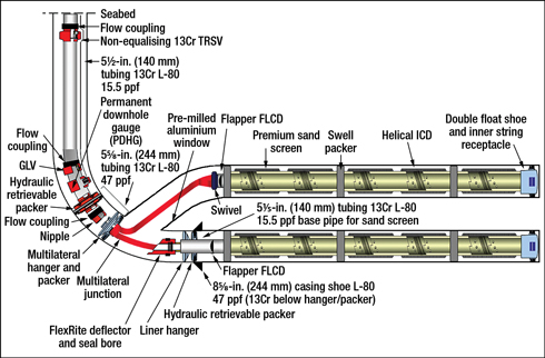
The upper completion consisted of the subsea tubing hanger, 5½-in. tubing and a retrievable production packer. The upper completion did not connect to the lower completion, which eliminated the time and risk of human error involved with spacing out tubing to stab into the lower completion while simultaneously landing the tubing hanger in the subsea wellhead. Figure 4 shows an early concept schematic of a standard dual-lateral Van Gogh completion.
 |
|
Fig. 4. Early conceptual Van Gogh dual-lateral completion schematic.
|
|
Multilateral junction requirements. The multilateral junction was to be located within the reservoir itself, which mandated a sealed junction to provide hydraulic integrity and prevent sand inflow through the junction.2
The Level 5 MLT installation requires 9 5⁄8-in. mainbore casing with 8½-in. drill-out, pre-milled casing window (aluminum external sleeve) and a sealed junction rated greater than 1,000 psi burst and collapse. The junction is located within the reservoir at high angle (typically horizontal) and the lateral completion can be installed in one trip. Premium screens run with internal wash string for cleanup circulation while the system has a compressive strength rating capable of running screen sections up to 1,450-ft long. Additionally, the installation is well-suited for harsh subsea conditions and involves minimal installation steps. The use of off-the-shelf technology leads to minimized lead times.
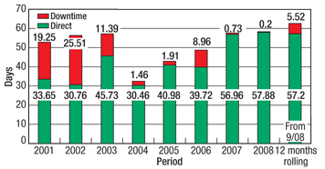
At the beginning of the project, the FlexRite system had been used for 84 subsea multilateral junction installations in the Norwegian sector of the North Sea with a NPT/OT rate of less than 1% (the NPT figures were based on a rolling average for 2007 and 2008, Fig. 5). This level 5 system met the Van Gogh requirements with very little customization and was available on short lead time to meet the project’s schedule.
 |
|
Fig. 5. Downtime vs. operational time for North Sea multilateral operations (level 5 junctions 2001–2009).
|
|
The selected system has a 5-trip installation process and is capable of handling thousands of feet of screen lengths and pushing the lateral completion into the horizontal section. This is possible because of a unique geometrical design on the flexible legs of the junction hanger, which consists of tubes formed in the shape of a “D.” This shape gives the junction high axial and torsion strength for compressive loading and also optimizes the flow area through the junction.
By definition, a TAML level 5 junction is mechanically and hydraulically sealed by the completion; this requires the installation of completion components that have a smaller ID than that of the wellbore casing. It is important that the sealing mechanism does not create a restriction to impede fluid flow at the anticipated production rates.3
The selected multilateral system is designed with several fail-safe features. For example, the mainbore casing/liner can be run and cemented with an inner string to enable safe orientation and cementing past the pre-milled window. MWD can be used on all orientation operations for a fail-safe redundancy and confirmation. The whipstock is run on a shear bolt that indicates a successful shear by means of a pressure reduction, and there are multiple options for whipstock retrieval. The safety shear joint enables a safe disconnect of the junction if the lateral completion becomes stuck above landing depth. Also, the flapper-type fluid-loss devices prevent mud losses after drilling each lateral and prevent cross-flow between laterals. In order to enable circulation while being run, lateral screens can be run with an inner string. Swivel enables torque-free rotation to orientate the junction. The system also incorporates a shear sleeve, which indicates that the flexible junction has reached landing depth.
Timeline and execution. The Van Gogh project required an aggressive deployment schedule that challenged the equipment supply chain during one of the busiest business cycles in the history of the petroleum industry.
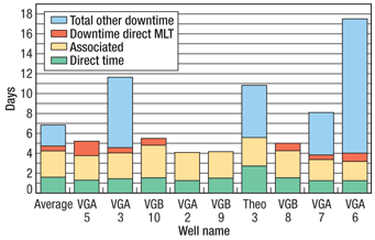
There were 57 hours of direct NPT associated with the multilateral installations out of a total installation time of more than 1,000 hours (5.7%), which are described in the following sections.
After the multilateral system was selected, the service provider had to supply all equipment for nine multilateral installations, much of which was required in advance to meet the demands of the batch drilling program. The tender for the multilateral equipment was accepted in December 2006 and drilling was scheduled to begin in January 2008. This schedule provided only 13 months to manufacture and deliver more than 160 major downhole multilateral assemblies to Perth, Australia.
The multilateral equipment was almost exclusively manufactured in Edmonton, Canada, which presented a logistical challenge because sea shipments averaged a two-month “door-to-door” delivery timeline. Remarkably, only 30% of equipment required air freight to meet the tight delivery schedule. Upon arrival in Perth, the components were assembled, pressure tested and finalized before mobilization by truck to the port.
The manufacture of a multilateral junction required specialized machining and forming processes. A major driver for Apache was using off-the-shelf technology; the equipment that Apache ordered had similar specifications to commonly used components for the Troll Field offshore Norway, so many of the components were already available.
The use of the two semi-submersible drilling rigs streamlined the construction of the multilateral wells and provided several cost-saving benefits as a result of the volume of activity present. Figure 6 shows a breakdown of installation times for each sequential well. Batch drilling created added importance on performance and equipment reliability because little to no time was available to change procedures or to manufacture or alter equipment. It was imperative that the equipment and process worked correctly the first time and throughout the entire development.
 |
|
Fig. 6. Van Gogh multilateral installation times by well.
|
|
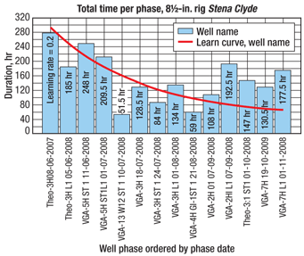
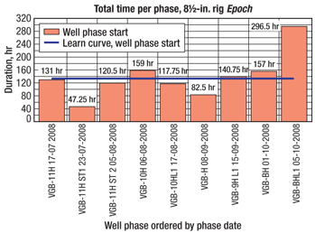
As shown in Fig. 7 and Fig. 8, over the development of the field, time spent during all stages of the 8 1/2-in. section generally decreased for each well. This decrease was the result of a constant focus on streamlining operations and continually applying lessons learned throughout the development.
 |
|
Fig. 7. Time per phase: Van Gogh A wells—81/2-in. section.
|
|
 |
|
Fig. 8. Time per phase: Van Gogh B wells—81/2-in. section.
|
|
Theo-3H exploration well. A decision was made very early in the Van Gogh development to use the Theo-3H exploration well as a production well. To conduct the production tests early enough to allow for sufficient reservoir analysis, Theo-3H was drilled in June 2007; nearly a full year before the remainder of the development. To meet a six-month delivery time, Theo 3H was developed as the world’s first 9 5/8-in. ReFlexRite system installation.
The 121/4-in. section of Theo-3H was drilled into the reservoir and, as part of the 9 5/8-in. casing string, two latch profiles were installed at potential multilateral junction locations. After cementing the casing conventionally, a combination cleanup and latch verification trip was performed to determine the orientation of the latch couplings. This operation was twofold. First, it enabled use of the system to analyze operating procedures and gather lessons learned well in advance of the true development. Second, it enabled the multilateral team to align the orientation of the milling and completion equipment in the workshop before sending it to the offshore rig. Theo-3H was sidetracked and completed as a multilateral in September–October 2008, 15 months after the installation of the 9 5/8-in. casing in the reservoir.
LESSONS LEARNED
Although the multilateral junction selected was a proven system with established run history and specifications, certain customizations were necessary with the Van Gogh development.
95/8-in. casing installation. On all previous FlexRite subsea system installations, the aluminum-wrapped casing window was run as part of a 10 3/4-by-9 5/8-in. liner string run in a 13 1/2-in. open hole. This assembly used 5-in.-OD drillpipe inner string, which enabled a MWD directional tool to be oriented to the window assembly, providing real-time feedback of the window orientation during landing operations. This is crucial to ensure that the window exit is placed at the correct orientation for milling the window and landing the junction in later steps. As the upper completions installed in the North Sea developments sealed into the 95/8-by-7-in. liner hanger above the flexible junction, there was no need for a production casing tieback to the wellhead.
In contrast, the Van Gogh completion method required the 9 5/8-in. casing to be sealed in the subsea wellhead; tiebacks were not an option because of Australian offshore well control policies. As a result, the windows were run as part of a 9 5/8-in. casing string. The standard subsea casing hanger running tool was not designed to apply the necessary torque to the casing string to orientate the pre-milled casing window before cementing, therefore a unique mechanism was required to be able to turn the casing string.
Working closely with the liner hanger vendor, Apache developed an inner profile sub to be run at the top of the 9 5/8-in. casing string. The wellhead landing profiles for all wells were then ordered to fit 10 3/4-in. production casing, rather than the standard 9 5/8-in. casing. The inner profile sub worked as a crossover, enabling a short pup of 10 3/4-in. casing to be run immediately above the profile sub, and the 9 5/8-in. casing to be run below. The casing (and inner string) were then run on a standard 9 5/8-in. liner running tool. Significant pre-project planning was involved to help ensure the success of this operation. Several independent torque and drag models were conducted to help ensure that the 9 5/8-in. casing would be successfully run into the wellbore and that it would be possible to orientate the window through a 90° build section. In reality, the installation and orientation proved to be extremely simple.
The batch operations sequence required that the main components of the inner string were racked back in the derrick to save additional time. On the third well, the 12 1/4-in. section was drilled through a trouble zone that resulted in the 9 5/8-in. casing becoming stuck while installing the 5-in. drillpipe inner string. The casing was successfully retrieved and all multilateral components were recovered for future operations. To further eliminate risk, the operation procedures were updated to include the use of a three-way handling sub to stroke the 9 5/8-in. casing routinely during the inner string installation on all remaining wells. No further problems were encountered with this operation.
Although this process required additional engineering and pre-project planning, it preserved the benefits of a pre-milled window eliminating the need for steel milling and the associated debris management.
Well cementing and mainbore cleanup operations. Standard level 5 multilateral installations use an inner string to provide a transmission path for the MWD orientation data and to eliminate the potential for cement to set in the window latch profiles. A special casing wiper dart had to be designed to wipe the various profiles and IDs of the casing because the cementing would be performed during the casing seal running trip, and the cement would pass through the window latch profiles. On the first two wells, concern about the integrity of the window seals caused the cement plugs not to be landed with sufficient force to seal in the casing float subs. Testing proved that all window assemblies were built to withstand a sufficiently high pressure to ensure the plugs would land and seal. In the first two wells, storm packers were temporarily installed as a safety measure, but no other wells required this additional step.
Since the wells were cemented conventionally, a wellbore clean-out trip was required before running the whipstock on a bolted mill assembly. Although this process generally added 12 to 14 hours of rig time to each well, eliminating the risk of not being unable to install the whipstock because of debris or of prematurely shearing the running bolt (and the subsequent fishing operations) made this an acceptable time allocation.
Lateral drilling. Point-the-bit rotary steerable systems (RSS) were used for all 12¼-in. and 8½-in. sections drilled on the Van Gogh project. In addition, most 8½-in. sections were logged using triple combination LWD tools, including gamma, resistivity and nuclear density.
For previous wells, the recommended procedure was to drill sufficient rathole in the formation outside the casing window exit to accommodate the full length of the RSS and MWD/LWD bottomhole assembly (BHA). Rotary steerable assemblies could be more than 100-ft long, but a calculated risk was taken to run them through the casing window with only a short 10-to 16-ft rathole to save trips and time. The Van Gogh wells were planned to be drilled in one bit run at a high ROP, as an additional trip to create a pilot hole would have been cost prohibitive.
Specific drilling parameters were developed, based on directional drilling experience in other operations, to determine the best window orientation and drilling assembly exit method to help ensure that the window exit did not contribute to premature failure of the drilling and logging tools. The result was a smooth and successful drill-out with no steering problems, no uncontrolled doglegs adjacent to the window aperture and no damage to the drilling tools. This result is largely credited to the elongated, controlled geometry of the pre-milled casing windows that were used. Despite being run through the multilateral junction, there was no notable difference in reliability was found between the 8½-in. drilling BHAs used in the two lateral legs.
Clean-out operations. It was determined early in the project that a dedicated clean-out trip would be conducted after retrieving the whipstock and before installing the completion deflector. A wellbore filtering tool was run as part of the clean-up BHA. This component enabled circulation from below to pass through spring-loaded valves on the bottom of the assembly, and when pulled out of the well, allowed fluid to pass through a very tight screen assembly, capturing debris.
In two cases, Van Gogh 3 and Theo 3H, the speed at which the tool was pulled out of the hole reduced the hydrostatic pressure on the open hole formation, resulting in formation collapse. This formation collapse was not realized until attempts were made to land the screens in the lateral. As a result, the liner hanger, junction and screens had to be retrieved and laid down, the completion deflector retrieved, and a whipstock re-installed. Only then could the lateral be re-drilled to ensure that the screens could be installed. In both cases, this process added nearly seven days of additional operations to recover.
Three steps were taken to eliminate this risk. Firstly, the clean-up run was only performed if the retrieval of the whipstock required excessive force. Secondly, if a clean-up run was required, the specific filtering tool was run near the top of the 9 5/8-in. section to eliminate the swabbing effect. Thirdly, the tripping speeds were regulated and fluid volumes were closely monitored for surge and swab effects.
Junction installation. One of the most important new innovations tailored for the Van Gogh installations was the incorporation of an inner wash string within the lateral screen section, which was run with the multilateral junction. A string of 2 7/8-in.-flush-joint tubing was run inside the 5½-in. base pipe of the lateral leg of the flexible junction hanger to allow circulation with returns if problems were encountered while running the lateral completion in the hole. The technique also facilitated the swapping of the water-based drilling mud for completion fluid after the screens were in place, reducing damage to the reservoir. This required considerable coordination between the liner-hanger vendor, casing-running vendor, completion engineers and the multilateral team to ensure that the space-out was accurate and the operations progressed smoothly.
At no point during the installations were any problems encountered with this step. All junctions were landed successfully and the lateral wellbores were circulated to completion fluid before setting the lateral liner hanger.
RESULTS
Offshore subsea wells in remote, isolated and environmentally-sensitive areas do not seem to be the most obvious candidates for new technology. The depth of experience of the multilateral service provider was critical to providing sound recommendations and operational planning to optimize the multilateral operations. Experienced project support was provided in Perth from the outset of the Van Gogh campaign combined with operational support provided largely from the multilateral group in Norway. As a result of 108 successful installations of the selected level 5 multilateral system in the North Sea, the vendor and operator multilateral team was supported to make informed decisions about the installation procedures.
Equally important to the pre-planning process was the capability of the operations team to take decisive action and rapidly change operating parameters, as necessary. The tight timeline involved with this project did not allow for extended studies or analysis. All decisions were made quickly and safely and, as a result of the efficient communication, operations were changed to help ensure that all lessons learned and updated methods were implemented at the next opportunity.
For the managers of the Van Gogh asset, knowledge, experience and communication were the key drivers that enabled them to make the dramatic
step forward and exploit the entire reservoir asset with multilateral production wells. Nine multilateral wells replaced 18 single wells, amounting to a significant saving in capex of about 24% for an additional 97% more reservoir exposure, requiring only 41% additional rig time. As a corollary, only 29% of the total project time was spent on creating and completing the upper lateral.
ACKNOWLEDGMENT
This paper was prepared from SPE/IADC 128314 presented at the 2010 SPE/IADC Drilling Conference and Exhibition held in New Orleans, Louisiana, February 2–4, 2010. The authors of this paper would like to thank all those involved with the successful Van Gogh project. Special consideration goes to Apache Australia for their invaluable collaborative input, as well as to the Halliburton teams in Australia and Norway for their contributions and support.
LITERATURE CITED
1 Lawrence, L., Redmond, B., Russel, R., McNeil, D., Reeves, M. and M. Hernandez, “Intelligent wired drill pipe provides significant improvements in drilling performance on offshore australia development,” OTC 20067 presented at the Offshore Technology Conference, Houston, Texas, USA, May 4–7, 2009.
2 Demong, K., Mason, S. and H. Al-Yami, “A rational approach to multilateral project planning,” SPE 77528 presented at the SPE Annual Technical Conference, San Antonio, Texas, USA, Sept. 29–Oct. 2, 2002.
3 Cuthbert, A., Hegreberg, J.M. and E. Skoglund, “Stacked multilateral system for the Troll Olje field – Development and case history,” SPE/IADC 79866 presented at the SPE/IADC Drilling Conference, Amsterdam, The Netherlands, Feb. 19–21, 2003.
4 Lowson, B., “Advanced window milling technology for multi-lateral applications,” Presented at the 6th One-Day Conference on Horizontal Well Technology Organized by the Canadian Section SPE and the Petroleum Society of CIM, HWSIG, Calgary, Alberta, Canada, Nov. 12, 1997.
|
THE AUTHORS
|
 |
Brett Lawrence is a Reservoir Engineer with Apache Energy Ltd. working on the Julimar / Wheatstone LNG Development. He joined Apache in 2005 as a Drilling Engineer based in Perth, Western Australia. Lawrence took on the role of Lead Drilling Engineer for the Van Gogh Development at its inception in 2006. He graduated from Curtin University of Technology in Western Australia with a Masters in Petroleum Engineering, a BEng Mining Engineering Degree and a BCom Finance Degree.
|
|
 |
Michael Zimmerman is the Eurasia Pacific regional manager for Multilateral Technology for Sperry Drilling, based in Perth, Australia. He holds a BSc degree in mechanical engineering from the University of Alberta in Edmonton, Canada. He has seven years of experience prior to Sperry Drilling working in multilateral drilling and completions, working on projects in South America, the North Sea, Kazakhstan, Japan and the Middle East.
|
|
 |
Andy Cuthbert graduated from the University of London in 1982 and is now in his 26th year in the oil industry. After leaving Schlumberger as a Directional Driller in 1994, he joined Sperry Drilling and became involved with multilateral technology in 1996 in the UK sector of the North Sea.
|
|
 |
Steven R. Fipke is the Global Operations Leader of Multilateral Technology (MLT) for Halliburton in Houston, TX. He holds a BSc degree in petroleum engineering from the University of Alberta in Canada. He has 10 years of experience working in multilateral drilling and completions.
|
|


