Reinventing the subsea production system: The first 20,000-psi SPS
Although an onshore production system rated for 20,000 psi exists, the subsea version had remained unrealized until a joint industry program was initiated in June 2015 between an operator in the Gulf of Mexico and OEM OneSubsea®, SLB’s subsea technologies, production and processing systems business.
Now commercially available, the 20,000-psi subsea production system (SPS) includes new technologies required to meet the demands of high-pressure, high-temperature (HPHT) conditions. Development included conducting rigorous qualification according to API Technical Report 17TR8 guidelines for equipment used in HPHT environments, which API defines as pressures greater than 15,000 psi or temperatures greater than 350o F.
In conjunction with HPHT qualification, an independent third-party (I3P) was commissioned to perform an engineering review of the equipment design, qualification and manufacturing plans, as required before the U.S. Bureau of Safety and Environmental Enforcement (BSEE) can approve operator plans or permits using the technology. The result of this extensive, comprehensive process, shown in Fig. 1, is a safer, more sustainable approach for producing 20,000-psi subsea fields.
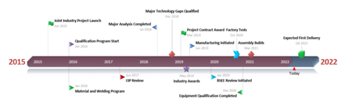
FIG. 1. Numerous major technology developments and regulatory approvals have been accomplished along the project’s expedited timeline.
Closing technology gaps with teamwork. Extracting hydrocarbons from an offshore deepwater well with shut-in pressures higher than 15,000 psi requires that every component of the entire subsea system can handle these conditions across drilling, installation, commissioning, production, intervention and transportation. This requirement has revealed many technology gaps to be addressed in developing a 20,000-psi SPS.
To tackle this broad challenge, a multidisciplinary global team was assembled. It was decided to develop all the necessary technologies and equipment, as possible, within the OEM’s organization to ensure that the development process and methods were consistent and easy to monitor to keep their progress on schedule. The team’s HPHT design strategy was to initially leverage existing lower-capacity designs by reinforcing the geometry and using stronger materials. This was supplemented by reducing overall loads by minimizing pressurized areas, pressure balancing and offsetting weight, which also supported manufacturing sustainability. Considering that the design team members were not necessarily located at the manufacturing and fabrication plants, a “design anywhere, manufacture anywhere” approach was also implemented, which was greatly facilitated by digitalization.
Highlights of the new technology development and qualification required for the 20,000-psi SPS are as follows:
Couplers. Traditional use of third-party technology for couplers was avoided through the development of interchangeable wet-mateable electric and hydraulic couplers with debris resistance. New robust seals also had to be developed, but overall, the number of parts in the couplers was minimized to keep tolerance stack-up low. These couplers enable more efficient footprint allocation, which allows fitting more downhole lines in the subsea tubing hanger.
Gate valves. Although OneSubsea’s more than 60 years of OEM experience included a 20,000-psi-rated gate valve for surface operations, the demands of the subsea environment required new gate and actuator designs. The full suite of HPHT gate valves developed for the 20,000-psi SPS includes 2-in. hydraulically-actuated and 5-in. manually and hydraulically actuated valves for the tree system. The manifold uses 5-in. hydraulically-actuated and 7-in. manual and hydraulic valves.
Connection systems. Two subsea tree-to-wellhead connector configurations were developed with the capacity to withstand extensive pressure, bending and tension loading conditions while efficiently interfacing with industry-recognized third-party lockdown profiles.
Four ROV-operable vertical clamp connection systems with dual metal gaskets were also developed with verified bending and torsional capacity at high pressures for use on the tree system, jumper and flowline connections and choke insert.
Multiphase flowmeter. Integrated into the main production flow path of the vertical monobore subsea tree system, the Vx Omni* subsea multiphase flowmeter enables HPHT subsea multiphase flow testing, with a venturi throat design that can measure the flowrates of gas, oil and water in any combination of proportions, from 0% to 100%. In addition to the reliability provided by having no moving parts and fully redundant electronics, 90% of the components are standardized, and their number is reduced by two-thirds from prior-generation designs, Fig. 2.
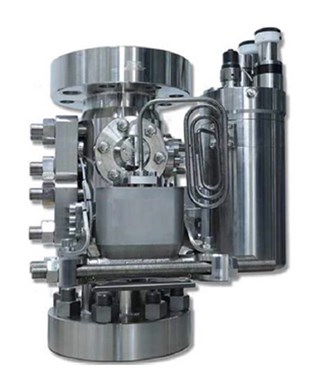
FIG. 2. Providing highly accurate measurement at the wellhead, the HPHT multiphase flowmeter forms the core of an interconnected, informed digital SPS.
Material and welding qualification program. Years before verification against industry and regulatory HPHT requirements was initiated, as part of the design process the multidisciplinary team collaborated to collect foundational data. The qualified materials include low-alloy steels (LAS) and nickel alloys, with nickel alloy cladding over LAS also qualified for use with all production equipment for ASTM Class HH steel. Additional testing was conducted for fastener documentation.
The results of this testing program documented material performance within air, sour production fluid, seawater and completion brine environments. From this basis, the fatigue characteristics and equipment performance in various environments were explored as an essential part of HPHT verification.
Integrated multiphase pumping system and production manifold. Rated to 16,500 psi, this permanently-installed large subsea structure houses a complete manifold section that connects up to four wells and a boosting section that enables increased field production, with a retrievable multiphase pump module, Fig. 3. This gravity-based structure will be supported on one of the largest suction piles in the Gulf of Mexico.
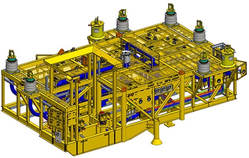
FIG. 3. The manifold pump station assembly integrates numerous components in a highly efficient configuration, from which weight has been shaved off.
Manufacturing the necessary large, heavy-wall forgings, pipes and fittings required developing and qualifying new manufacturing methods. The process valves for operating the pump were similarly qualified for a 7 1/6-in. bore size, and they incorporate a nonreturn valve and fail-open and fail-close hydraulic spring-return gate valves.
Additional new subsystems include a flow mixer to suppress slugs in the multiphase flow and a pressure equalization circuit, for safer pressurization and depressurization of the pump process section when using the pump control system during intervention. At a system level, the new control logic approach reduces the number of components by using the production tree subsea control module to control manifold valves within the production manifolds and the integrated manifold pump station.
Pump module. Installed with the integrated manifold pump station, the pump module is a retrievable subsea structure featuring a helicoaxial multiphase pump with a maximum flow capacity of 120,000 bopd, 2,320 psi of design differential pressure and a gas volume fraction range from 0% to 100%, Fig. 4. The pump housing is joined to the motor housing through a new flange,with a secure, dual-metal gasket. Inside the housing is an electric motor with 4 MW of shaft power that drives a multistage impelled pump joined by flexible coupling.
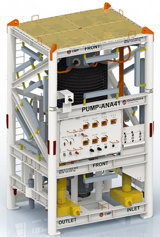
FIG. 4. Based on the rotodynamic pumping principle and using helicoaxial technology, the pump module is inherently robust and wear-resistant.
The pump’s dielectric hydraulic fluid system lubricates the pump, cools the motor and acts as a barrier to prevent process fluid from entering the motor by maintaining a constant overpressure during all operation and intervention modes of the pump. The fluid is supplied from a topside hydraulic power unit through the umbilical. Mechanical valves ensure that the overpressure is maintained throughout rapid increases or decreases of process pressure in the pump.
For flow control, the pump uses a single-phase flowmeter on the discharge side.
Vertical monobore tree. The subsea tree was designed to house many of these newly developed technologies in a compact package that ensures that the total weight and footprint are within the capabilities of the system’s handling and testing facilities, Fig. 5. Its other major innovation is the tubing hanger system, with lockdown and orientation packages in a slim annular design, which, in combination with the small-footprint couplers that were developed, allows space for 13 downhole lines.
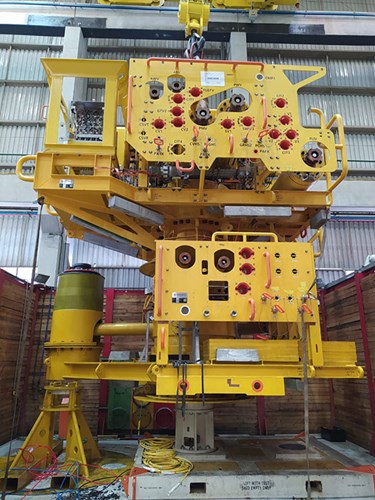
FIG. 5. The 20,000-psi vertical monobore tree is another industry-first successor to OneSubsea’s introduction of the first 15,000-psi subsea vertical monobore tree, two decades ago.
Packaging the 20,000-psi subsystems and demonstrating standards compliance. Project execution during the detailed engineering phase had to meet several new challenges while staying on time and on cost. An additional constraint was accounting for the added weight of the components required for the vertical monobore tree system to control and direct fluid flow at the elevated pressures.
The design strategy to improve on lower-rated designs by increasing wall thickness and using stronger, denser materials had the potential to add significant weight. But the system still had to be transportable on water, land and air; conform to offshore rig deployment and testing capacity; and dimensionally fit the maximum height allowance and fatigue loads of cranes.
Our innovative annulus routing path for shortening the tubing head spool by placing the primary annulus valves horizontally aligned to each other, instead of the conventional vertical arrangement, reduced both height and weight. Establishing self-balancing layouts mitigated balance weight requirements, and the weight of the thermal insulation on the pipework of the manifold structural frame was optimized via thermal analysis studies.
It was during this project phase that compliance to BSEE regulatory guidance, issued as Notices to Lessees and Operators, was addressed. A team of the SPS subject matter experts developed a foundational design philosophy toward globally meeting HPHT design requirements, including previous alignment with API 17TR8, that would eliminate numerous interpretation cycles. The coordination and collaboration between all three entities was essential in establishing the ground rules by which planning, execution and reviews involving the I3P, operator and OEM would impact the schedule. The potential consequence of missing just a single element within a guideline or standard could delay equipment delivery by months, so maintaining this alignment has been critical to maintaining timely progress.
The operator also requested additional testing to reduce the risks associated with the first deployment of equipment that has not been field-tested. Because it would be highly inefficient to use the complete SPS assembly for testing parts, qualification test fixtures with equivalent configurations, forces, friction properties, debris introduction and other aspects were used.
Leveraging digitalization for optimization and sustainability. In line with the industry’s trend toward digitalization, emerging software solutions were employed to significantly improve all aspects across every phase of the project. For example, advanced finite element methods were used to analyze complex components and assemblies. Admittedly, HPHT systems exert higher stresses and deflections on structures, but traditional/conservative methods of analysis output requirements for high-cost materials, with high yield strength and unnecessarily thick cross-sections to support pressures. The software enabled conducting realistic modeling of load cases without the need to build a physical prototype.
Virtual reality (VR) technology was used from the early stages of the project to provide an immersive interactive experience with the production equipment and simulate assembly operations and subsea operations, such as ROV interfacing. VR also supported a live feed of the assembly, testing and manufacturing processes to engineers and other subject matter experts for remote real-time witnessing. This was especially useful in connecting with the I3P and operator when travel restrictions were posed by the COVID-19 pandemic.
Having digital tools for modeling and simulation also contributed to sustainability. This approach accelerated the ability to affect weight reductions, as previously mentioned, and shortened the prototype stage, both of which inherently reduced embodied carbon emissions. Similarly, a new tooling system to reduce operator installation time will help minimize carbon emissions from offshore facilities and vessel usage during those operations.
Meeting fabrication challenges with upgraded facilities and digital capabilities. The equipment-build phase included upgrading the OEM manufacturing plants to state-of-the-art manufacturing and testing facilities to address the size and complexity of equipment that was beyond their previous 15,000-psi applications. The upgrade also included the testing facilities. In particular, the test cells increased their pressure capacity, footprint, and depth and added remote monitoring tools. New processes were developed, such as using custom fastener preload equipment, ultrasonic inspection methods and automated remote monitoring and testing capabilities for the high-pressure test cells.
Virtual-build simulation was incorporated in the manufacturing process to first assemble products in a 3D virtual environment once the top-level assembly models and procedure were released. This approach requires only a single engineer, not an entire physical process and necessary materials and personnel, to confirm sequence optimization, verify access to connections for validation, check for incompatibility between assembly components and tooling, and confirm that all areas for improvement are identified before starting the physical build.
All findings are extensively documented and available across the design, manufacture, assembly and test teams. The virtual build also helps in reducing HSE risks, such as those posed by handling concerns. Following a “virtual first” process has proactively mitigated sticking points in the physical process to reduce downtime during subsequent assembly and in turn, reduce nonconformance issues.
New capabilities introduced across the industry. The new 20,000-psi subsea production system is not just for Gulf of Mexico application. The components are already commercially available and meet most current regulatory requirements and design guidelines for other HPHT offshore developments. The recently published third edition of API 17TR8 provides additional design guidance, with which this system was proactively designed to already comply. WO
*Mark of SLB.
ACKNOWLEDGEMENT
This article contains elements from OTC paper 32024-MS, which was presented at the Offshore Technology Conference, May 2–5, 2022.
- Advancing offshore decarbonization through electrification of FPSOs (March 2024)
- Digital transformation/Late-life optimization: Harnessing data-driven strategies for late-life optimization (March 2024)
- The reserves replacement dilemma: Can intelligent digital technologies fill the supply gap? (March 2024)
- What's new in production (February 2024)
- Subsea technology- Corrosion monitoring: From failure to success (February 2024)
- Digital tool kit enhances real-time decision-making to improve drilling efficiency and performance (February 2024)
- Applying ultra-deep LWD resistivity technology successfully in a SAGD operation (May 2019)
- Adoption of wireless intelligent completions advances (May 2019)
- Majors double down as takeaway crunch eases (April 2019)
- What’s new in well logging and formation evaluation (April 2019)
- Qualification of a 20,000-psi subsea BOP: A collaborative approach (February 2019)
- ConocoPhillips’ Greg Leveille sees rapid trajectory of technical advancement continuing (February 2019)

