Gel displacement supports subsea flowline decommissioning without production interruption
ELISABETH BYREMO HELLEREN, Halliburton
LATE-LIFE FLOWLINE CLEANUP
In a North Sea case, Halliburton applied a chemically engineered gel displacement method to remove hydrocarbons from subsea flowlines, without production interruption, diver intervention or installation of pig launcher-receiver equipment. The project demonstrates an alternative technical approach for late-life subsea assets under restricted conditions. Mature offshore developments increasingly face scenarios in which subsea flowlines require asset retirement, while adjacent infrastructure remains operational. Conventional hydrocarbon removal methods—such as mechanical pigs or topside routing—often prove impractical, due to access limitations, third-party interfaces or operational risks.
End-of-life treatment of offshore subsea infrastructure remains a complex challenge. Offshore wells typically undergo abandonment as discrete activities. Associated flowlines often require treatment, while other parts of the network remain in production. This condition can restrict conventional hydrocarbon removal methods.
Industry practice commonly relies on mechanical pigs or fluid displacement to remove hydrocarbons and debris before abandonment. However, many legacy flowlines no longer support mechanical pig passage due to rerouting, wax deposition or removal of pig launcher-receiver facilities. In such cases, operators require alternative technical approaches that meet environmental discharge criteria, while they limit offshore intervention and operational disruption.
The North Sea case involved a subsea flowline system that was decommissioned with a chemically engineered gel displacement method—all while interconnected systems remained in production. This approach may also apply to other late-life projects, in which hydrocarbon removal must meet regulatory requirements.
NORTH SEA CONSTRAINTS
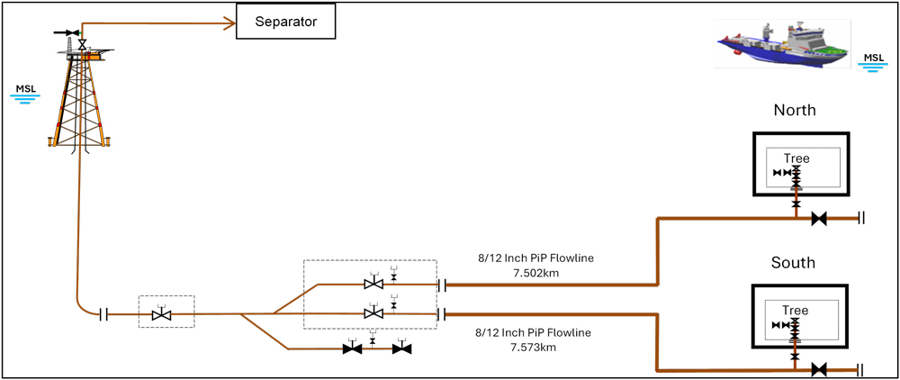
The project involved two 8-in. pipe-in-pipe, multiphase gas-condensate flowlines in the Norwegian sector of the North Sea that required abandonment. The flowlines connected subsea wells to a manifold tied back to a producing platform, Fig. 1. Although production from the wells had ceased several years earlier, hydrocarbons remained in the flowlines because they had not been cleaned and prepared for abandonment.
The flowlines were originally configured for pig passage but later rerouted, and pigging facilities were removed. Therefore, the flowlines required hydrocarbon removal and preparation for asset retirement. This work could not be allowed to affect adjacent producing assets. Typical objectives included the removal of movable debris and hydrocarbons and the replacement of internal contents with treated seawater to meet offshore discharge targets. After cleaning, subsea flowlines and pipelines usually remain abandoned on the seabed, filled with seawater and treated to reduce corrosion. A typical cleanliness target is about 30 ppm oil in water.
GEL DISPLACEMENT SELECTION
The team evaluated several technical approaches as part of the gel displacement selection process.
Option 1. The team considered routing flowline contents to the platform topsides. This option posed schedule and prioritization challenges, due to the platform being operated by a third party. It also required new topsides pipework and risked contamination of production fluids from other fields. The team did not select this option, because it carried high risk, required agreement among multiple parties, and increased project cost.
Option 2. The team considered using mechanical pigs. This option was not practical, due to the subsea pig launcher-receivers being diver-operated and incompatible with remotely operated vehicles. This option required costly modifications to the pig launcher-receivers or the use of a dive vessel. It also required a temporary topsides pig launcher-receiver and associated pipework, and so the team did not select this option.
Option 3. The team considered using an oil tanker to receive the flowline contents. The team ultimately categorized this option as expensive and impractical, due to required crude stabilization and potentially required gas-phase separation and management.
Option 4. The team considered using a closed-loop displacement approach, designed by Halliburton, to route flowline contents to a disposal well, while limiting topside interaction to a small riser volume. This option relied on a chemically engineered gel system, to displace hydrocarbons and clean the flowlines internally. After technical and commercial evaluation, the team determined that this approach met project constraints.
RISK CONTROL STRATEGY
The selected approach introduced several technical risks that required mitigation:
- Crosslinked gel entering the disposal well formation could cause blockage or undesirable formation fractures.
- Back pressure, generated by the gel slug at the disposal well choke and reduced-bore tubing, could exceed the flowline system design pressure.
- Wax deposition in the flowline could reduce displacement efficiency and increase treatment volume requirements.
- Low subsea temperatures and flowline contents could promote gas hydrate formation and blockage.
Because of the restricted subsea injection point, the gel had to be pumped in a low-viscosity, linear state and crosslinked subsea, just before flowline entry, to increase viscosity for effective cleaning. The gel would subsequently break down, to reduce viscosity before injection into the disposal well. At low subsea temperatures, the hydrate inhibitor in the gel base fluid was critical. Halliburton developed an engineered system that combined a low-residue gelling agent, hydrate inhibitor, crosslinker, buffer agent and breaker fluid. The formulation maintained the required viscosity profile throughout the operation.
GEL BREAK VERIFICATION
The base-case operation methodology included three steps:
- Propel a gel slug from a vessel through the south tree and displace flowline contents to the north tree, well and formation.
- Inject crosslinker into the gel slug, after the south tree choke and before flowline entry, to improve cleaning efficiency.
- Reduce flowrate before the viscous gel slug reaches the north tree and choke, and inject gel breaker fluid from a second vessel, through a 1-in. hot-stab connection.
To verify gel break timing, laboratory tests were conducted to evaluate breaker performance, for a range of concentrations and temperatures. Initial tests took place at the Halliburton Technology Center in Pune, India. Confirmation tests followed this, at the Operations Center laboratory in Stavanger, Norway.
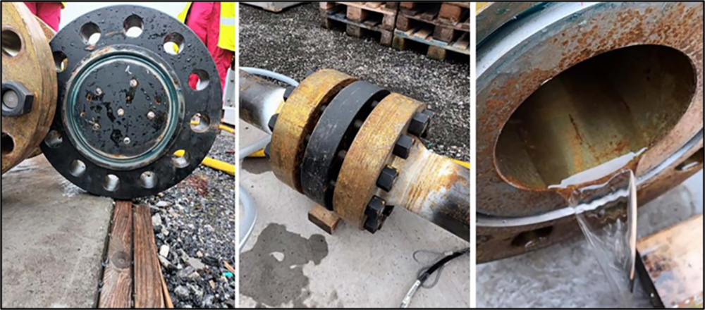
A full-scale yard trial, at the company’s operations center in Stavanger, Norway, simulated subsea flowline geometry and choke conditions under winter temperature conditions. The trial confirmed acceptable displacement flowrates and breaker injection volumes. These activities reduced uncertainty related to pressure response, gel-break behavior and well-interface conditions.
Accurate estimation of flowline internal volume proved critical to operational timing. Wax deposition reduced effective bore and influenced gel arrival calculations. Engineers completed sensitivity analyses to account for this uncertainty, Fig. 2.
After completion of calculations, designs, laboratory tests, yard trials, risk assessments, contingency plans and simultaneous operations discussions, the team finalized detailed engineering procedures and held a hazard and operability meeting. The offshore execution phase then began.
OFFSHORE EXECUTION
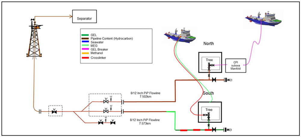
The offshore scope comprised two workstreams: a flowline scope, executed from two vessels, and a riser scope, from one vessel and the platform. Platform involvement in the flowline scope remained minimal.
Flowline flushing scope. Vessel 1 had two downlines and a pumping spread, with the following specifications:
- 3-in. downline for linear gel, preflush, postflush and filtered seawater
- 1/2-in. downline for crosslinker, connected to the south tree after the choke.
Vessel 2 had one downline and a pumping spread with a 1/2-in. downline, for the breaker injection point connected to the tree choke, Fig, 3.
Riser flushing scope. Vessel 1 had two downlines and a pumping spread, with the following specifications:
- 2-in. downline for linear gel, preflush, postflush and injection of chemically treated filtered seawater, to preserve the riser in situ
- 1-in. downline for crosslinker injection.
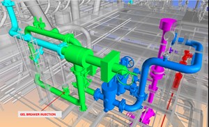 Fig. 4. Riser flushing layout, showing gel arrival at the platform.
Both downlines connected to a stab in the riser base, at the future connection point, through a retrofit flange with a large-bore remotely operated vehicle (ROV) stab receptacle.
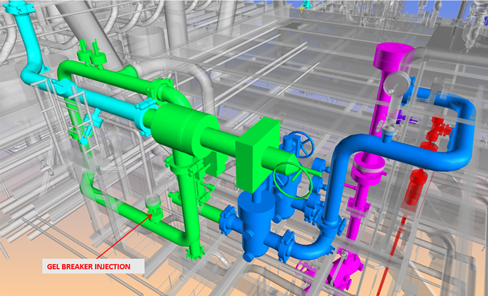
The platform pumping spread featured a topside injection point for gel breaker fluid, before the choke and separator, Fig. 4. The method displaced hydrocarbons from the south tree toward the north tree and the disposal well. The crosslinker was injected immediately before flowline entry. As the gel slug approached the disposal well, flowrate reduction and breaker injection reduced gel viscosity before well entry.
Riser activities used chemically treated and filtered seawater to preserve the riser, which remained in place until the end of field life. A retrofit subsea connector, with an ROV-operable large-bore stab, allowed these activities to proceed without diver support. Platform involvement remained minimal and was limited to valve operation and breaker injection, upstream of the separator.
HYDROCARBON REMOVAL RESULTS
Post‑operation sample analysis from flowlines and topside samples confirmed hydrocarbon removal and achievement of offshore discharge targets. The project met all objectives without health, safety or environmental incidents.
Key outcomes included:
- Hydrocarbons were removed from dual pipe-in-pipe flowlines, while adjacent assets remained in production.
- Typical cleanliness criteria were ~30 ppm oil in water, consistent with offshore produced-water discharge targets.
- The breaker solution reduced gel viscosity, without affecting the disposal-well formation.
- The breaker was injected one minute before the anticipated gel arrival at the wellhead connection.
- Operations were completed without dive support vessels, pig launcher-receivers or tanker support.
- Chemical volume remained limited to approximately 25 bbl of water-based gel.
- Treated seawater preserved the riser for long-term in-situ storage.
- The project demonstrated a repeatable technical approach for similar subsea configurations.
- The flowlines remained isolated and ready for final asset retirement activities.
PRACTICAL DECOMMISSIONING OPTION
This North Sea case demonstrates that chemically engineered gel displacement offers a technical alternative for subsea flowline asset retirement, when conventional methods are limited.
The approach removed enough hydrocarbons to reach the 30-ppm oil-in-water target, reduced offshore complexity and avoided production interruption, diver intervention, pig launcher-receivers and tanker support. Laboratory testing, yard trials and offshore execution confirmed the method managed viscosity, pressure response and disposal well interface risks. For late-life subsea systems with restricted access or limited topsides options, gel displacement offers a field-tested approach to hydrocarbon removal and asset retirement readiness.

ELISABETH BYREMO HELLEREN is a principal technical professional in Halliburton’s Pipeline and Process Services product line in Stavanger, Norway. She has extensive experience in engineering and project management in the offshore oil and gas project lifecycle, including pre-commissioning, commissioning and operational delivery. Her work focuses on offshore execution and technical integrity.
Related Articles- First Oil: Low expectations for new UK prime minister (July)
- Why decommissioning is really a waste management problem (June)
- Realizing efficient well abandonment safely: How modular systems redefine rig-less subsea and mudline well decommissioning (June)
- A Baker Hughes executive assesses the electrification effort (May)
- Umbilical‑less subsea completions: Reduced interface risk with eROCS and OTHOS (April)
- Beyond the permit window: How data-led integrity is redefining offshore pipeline life extension (April)