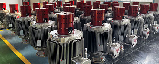
More production with less power and noise
In response to growing concerns related to the future of energy production and climate change, governments in general have deployed plans for reducing their carbon footprints in their countries of operation, featuring increased interests in preserving the ecosystem. These plans include, among other initiatives, the implementation of more energy-efficient technologies across different industries—within which the oil and gas (O&G) sector is already leading a number of sustainability projects that have had an impact on short- and long-term exploration and production techniques.
The production segment has revolutionized the concept of efficiency in artificial lift systems (ALS) during the last 10 years, as it adapts horizontally to different types of lift currently used to extract fluids to surface. A recent ALS motor technology advancement, the permanent magnet motor (PMM), has proven to contribute to streamlining operations and delivering significant energy savings. This article will establish the main differences between PMMs and traditional induction motors (IMs). It will explore a case study that showcases improvements on lift efficiency and demonstrates how other collateral aspects were a direct result of the implementation of this technology—including reduced maintenance, flow assurance, and more.
Powerful magnets overtake conventional induction motors. One of the constant requests from O&G is the deployment of technologies that maximize production and reduce operational costs. ALS service companies have mainly been working on the development of new products to ultimately increase production. These primarily include reductions of operational costs, due to the combined effects of high oil prices with accelerated exploration and production campaigns, leading to the postponement of research and development agendas. Since 2015, instability and extended low oil prices did not support major R&D investments and instead promoted the focus on technologies offering greater efficiencies and the ever desirable “lower operations costs.”
More recently, higher oil prices, combined with established environmental, social and governance policies, are proving to be the perfect coalition where ALS service companies and operators can make the big jump to develop and deploy more efficient solutions. Existent, proven technology was identified as an opportunity to design a unique line of higher-efficiency drive-head units for progressing cavity pumping (PCP) systems.
PMM technology is based on the use of rare-earth permanent magnets that create a continuous magnetic field. The rare-earth minerals include 17 metallic elements with unusual fluorescent, conductive and magnetic properties, making them useful when alloyed or mixed in small quantities with more common metals, such as iron.1 Neodymium (Nd) is one of these rare-earth elements, and since the 1980s has been combined with nickel to manufacture hybrid batteries. These batteries can be recharged repeatedly while holding a significant energy relative to their volume (size). As of today, Nd is well known as one of the strongest permanent magnets in the market and has been utilized in portable electronics, hybrid cars, speaker systems, and wind-turbine motors. Because of its magnetic properties, Nd has been incorporated into electric motor designs to improve energy and transmission efficiency while in operation.
Conventional PCP drive-head units are traditionally driven by electric induction motors (IMs), which operate at high rotational speeds and have two main components—the stator and rotor. The stator is an outer, non-moving chamber that creates a magnetic force through alternating current that “induces” the rotor to spin. The stator has a cylinder shape formed by a ring of electromagnets, slotted steel, and iron layers. Copper wire is wound through the cylinder’s interior, creating the magnetic poles. The rotor consists of a group of electromagnets, arranged around a cylinder, that rotates, due to the magnetic field produced by the stator.2
These motors are typically combined with belts and sheaved transmission systems that operate within a specified speed range. Unfortunately, the transmission from the electric motors to a PCP drive head—through the belts and sheaves up to the polished rod—is inefficient. This creates significant energy losses, resulting in a deficit waste of electrical energy. Since 2008, several electric motor manufacturers have embarked on a journey to optimize the transmission of rotating energy from the electric motor to the system. It is also well known that by using a direct-drive head system, transmission losses are reduced enormously in a rotational machine. Concurrently, this also creates challenging conditions, such as having drive-head units strong enough to hold their integrity while operating at higher speeds. Then, on the lower end, this, in turn, requires an increased capability from the electric motor to supply higher torque outputs.

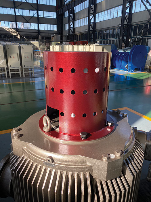
No transmission, more power transfers. The PMM is a technology that simply modifies the widely used IM. PMM designs include the same components, such as the rotor and stator. However, in the PMM, the rotor can be a solid piece, featuring small sections of Nd encased on the rotor surface,3 Fig. 1.
Nd sections in the PMMs are permanently magnetized, eliminating the requirement to inject large amounts of current required to create the magnetic field between the rotor and the stator, as with all traditional IMs. With a more magnetic material in the rotor, slippage in the PMM motor is eliminated. This helps to reach higher efficiencies in the system, starting at 94%. As a result of these modifications on the rotor’s raw material, the electric motor offers higher torque at significantly lower speeds.
Through this achievement, the transmission system (belts, pulleys, and gear reducers) is eliminated from the supplemental components required by the electric motor, Fig. 2. This indirectly reduces more than 50% of the inefficiencies of the electric motor when transmitting speed, torque and power to the PCP drive head while in operation. Because of the sheave-less condition, the equipment will also be safer, featuring less noise and less carbon footprint throughout its operational life.
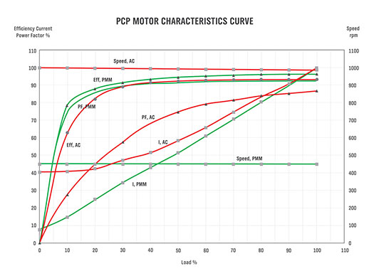
Perfect fit for oil and gas wells. Expanded PMM development brought several re-evaluations of IM performance, based on parameters such as power factor (PF), efficiency (Eff), current and how these parameters depend on operational speed. Figure 3 shows a comparison between PMM and IM parameters. The key findings are: 1) PMM PF is substantially greater than IM PF across the load percentage curves; 2) PMM Eff is generally greater than IM Eff. When operating at lower speeds, IMs need double operational speeds to reach the efficiency of PMMs; and 3) PMMs need less current to offer a higher efficient performance over IMs. IMs require higher currents, leading to increased energy consumption.
From an applications standpoint, there are several benefits related to PMM production advantages versus IMs:
- PMM efficiency and power-factor savings are highly comparable to IMs in heavy oil wells at early stages of production, where high operational speeds are required.
- For low-speed applications, such as heavy oil wells in late stages, PMMs can run as low as 10 rpm with constant-rated torque output and no slippage—regardless of operational speed. However, IMs cannot run at low rpms without compromising output torque. In addition, a heavily loaded IM system experiences significant belt wear and loss of transmission efficiency, because slip ratios are highest during heavy loads—resulting in additional maintenance and downtime.
- For low-production wells, PMMs can run continuously at ultra-low rpms. This eliminates the need for production cycles and non-productive time periods, avoiding high-start power consumption.
- By eliminating mechanical breaks and moving parts, such as belts, sheaves and gears, the probability of these component failures and their related downtime are thus eliminated.
- Even when comparing the most basic field designs, PMMs generate significantly less noise than IMs equipped with moving parts, such as belts and sheaves that produce noise during operation.
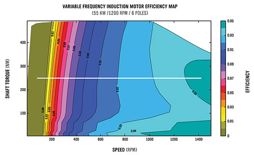
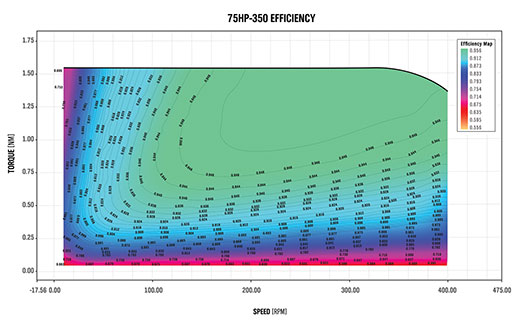
At high or low speeds, PMMs win. Establishing the difference between PMM and IM performance is apparent through the IM MAP graph. This diagram shows the combined effect of three parameters of electric motors strictly related to its design when in operation, Fig. 4. The MAP also demonstrates the efficiency for a typical high-frequency IM at 75 hp, 1,200 rpm, and six poles. By analyzing the graph, notice how IM efficiency is directly related to IM speed—higher IM speeds translate higher efficiency. IM efficiency is highly affected under low-speed scenarios. This means an IM will have inefficiencies greater than 20%, when operational speeds are lower than 100 rpm. On the other hand, the MAP graph below shows the efficiency for PMMs at 75 hp and 350 rpm, Fig. 5.
This graph shows how higher efficiencies are reached with the PMM, even when operating at speeds as low as 100 rpm. It is also clear that with higher torques and mid-to-high speeds, the PMM efficiency reaches values around the 0.94 percentile. Keep in mind, these values are extremely difficult to achieve via IM, even when operating at maximum-rated speeds. As a result, the PMM has proven exceptionally more efficient than IMs.
Romanian fields prove value. Proof of these efficiency benefits is exemplified by a field test from an operator in Romania, featuring a population of valuable oil wells producing through PCP systems. In total, three units were chosen to be installed as a field trial. Selected assets included wells located in southern and central Romania. Their flowrates proposed additional parameters for well selection, specifically featuring a range from 80 m3/d to 150 m3/d. During the implementation stage, data were captured directly from the wellsites via a SCADA system. The operational well data collected were utilized as a benchmark to corroborate PMM energy-savings performance versus conventional PCP operational data, as garnered from the surface units previously installed on these wells.
Less noise, less maintenance, more safety. The project implementation involved the installation of three PMM units as surface drives on wells with PCP systems already deployed. The case study included the complete well commissioning. Data collection comprised operational speed, fluid production, maintenance frequency, and energy consumption. The results indicated improvements in energy efficiencies by reducing their electrical power consumption and their ability to remotely optimize and control the well via variable frequency drive. Measurements conducted before and after the project development established a baseline for PMM improvements of noise levels, and power consumption achieved, compared to the PCPs.
In terms of energy consumption, the three wells showed reductions between 4% and 10%, Fig. 6a. It is important to mention that the wells with PMMs are currently operating at lower speeds, as compared when the conventional PCPs were installed. The fact that these wells are operating at slower speeds while delivering the same flowrates is convincing proof of PMM efficiencies over IMs for PCPs.
In one of the wells, the noise level measurements showed a 45% noise reduction from 73.20 dB to 39.85 dB. The other two wells showed noise reductions of 21% and 38%, respectively. These results are summarized on Fig. 6b.
Prior to PMM installation, the conventional PCP drive heads required two scheduled maintenance sessions per year. This routine included belt replacements (two sets), oil changes (eight liters each) and about six hours of labor per year. Noticeably reduced maintenance requirements following the PMM installations, compared to the frequent belt-replacement needs of conventional PCPs, were observed in this project. PMMs require no belts or related maintenance upkeep for oil changes (3 l) and associated annual labor (2 hr). The annual average savings for PMMs, compared to conventional PCP, is over 70%.
These wells used to have one major intervention per year. After more than a year since the PMM installations, no additional interventions were needed in these wells. This resulted in total savings of approximately $38,000 or about 95% of the total annual expenses for well intervention in these three wells. In addition to these operational benefits, PMMs also represent a reduction of carbon emissions while also enhancing safety by eliminating human exposure—thus highlighting that PMMs are much safer to operate, with no belts subject to becoming loose or moving parts exposing the system to potential failure.
What’s next for ALS and PMMs? PMMs are significantly more efficient than IMs in the majority of evaluated scenarios versus when installing an IM. They require less current while delivering improved performance over IMs. IMs need a higher current ratio, which leads on higher energy consumption. The application of new technology, such as PMM drives as alternatives to IMs, delivered less noise in operation and provided additional savings in energy consumption.

By installing Weatherford PMMs, the operator was able to reduce noise emissions 38% and reduce energy usage 9%, on average, on two well applications. After more than one year since PMM installations, no additional interventions were needed on these wells. This resulted in a total savings of around $38,000 and about 95% of total annual expenses for well intervention for the three wells. The expansion of PMM development inspired several re-evaluations of IM performance concerning parameters such as PF, Eff, current and their dependency on the unit’s operational speed.
In South America, asset owners are moving aggressively toward this technology. During 2021, two major oilfield operators procured more than 150 PMMs to be deployed over the next three years. The transition to PMM motors has already begun!
REFERENCES
- Science History Institute_Science Matters: The Case of Rare Earth Elements History and Future of Rare Earth Elements | Science History Institute
- Motors 101: How Do AC Induction Motors Work? (powerelectric.com)
- https://www.horizontechnology.biz/blog/induction-vs-permanent-magnet-motor-efficiency-auto-electrification


- Shifting from calendar to usage-based maintenance: Proven results that demand your attention (June)
- Executive viewpoint: Methane monitoring goes digital (May)
- Simplified intelligent completion architectures improve zonal control economics (May)
- John Henry vs the steam drill: Will the robots win? (May)
- Why oil and gas companies should invest in ruggedized edge computing (May)
- Baker Hughes Senior V.P. touts benefits of autonomous well construction (April)

