Subsea technology- Corrosion monitoring: From failure to success
AUDUN O. PEDERSEN and GEIR INSTANES, ClampOn
A measurement principle for full-area wall thickness monitoring. In the early 2000s, ClampOn developed their CEM Corrosion-Erosion Monitor, a non-intrusive instrument for monitoring the wall thickness of pipes throughout a decades-long service life. Early trials were based on through-thickness ultrasound, which was at the time identified as the most prominent principle for thickness measurement of the actual pipe wall.
Recording of traditional C-scans with fine resolution requires many measurements over the wall surface, either performed by inspection personnel or by large grid arrays of point monitoring transducers. ClampOn soon experienced an impossible trade-off between sufficient density of measurement points and thus probability of detection, on the one hand, and reasonable complexity of the monitoring system on the other. An acceptable balance could not be struck between data quality, reliability and cost when basing a monitoring system on point measurements. Not least for subsea applications, it was necessary to find an alternative wall thickness monitoring technology that could provide acceptable area coverage using instrumentation that would work reliably over decades.
Acoustic guided Lamb waves were an emerging technology for measurement and flaw detection across continuous areas of plate structures and pipe walls. A relatively small number of ultrasound transducers can be placed around a monitored area, transmitting guided Lamb waves between them. This was recognized as a potentially considerable improvement over the conventional point measurement methods.
Guided Lamb waves also proved to be robust against internal and external surface roughness of the pipe wall. This had been seen as problematic for the through-thickness ultrasound technique, especially for permanently installed systems and for probes operated remotely via crawlers or ROVs. ClampOn initiated collaboration with suppliers and academic research groups working with acoustic guided waves worldwide. Several approaches were tried in laboratory studies to identify a guided-wave measurement technique that would have the sensitivity and robustness needed for industrial wall thickness monitoring.
The efforts brought the company in contact with a highly capable scientific group that has understanding of industrial applications. The group proposed exploiting the dispersion property of the fundamental flexural guided Lamb wave mode. At an ultrasonic frequency known as the constant group velocity (CGV) point, the time-of-flight of a fundamental flexural wave is constant (independent of wall thickness), while its phase velocity depends upon wall thickness.
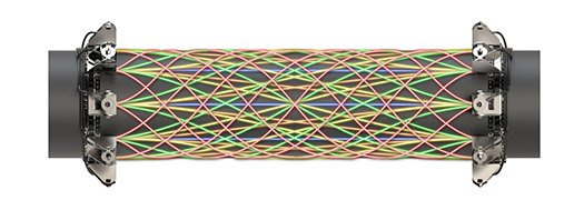
A pair of ultrasound transducers can be installed permanently on a pipe wall surface, and an acoustic guided-wave signal (Fig. 1) can be transmitted between them, following the contour of the wall. An initial propagated signal can be recorded as a baseline measurement and associated with a known mean wall thickness between the two transducers. When this guided-wave signal transmission is repeated, a phase change in the received signal can be measured with high sensitivity and encodes a change in the average phase velocity along the guided-wave propagation path. Such a measured change in signal phase can be converted to a change in mean wall thickness across an elliptical area of sensitivity between the transmitting and receiving ultrasound transducers. The area of sensitivity has been shown to be much wider than the footprints of the ultrasound transducers.
From physical measurement principle to industrial instrumentation. The CGV point method was tested extensively in laboratory trials. Parameters such as temperature, coating, and fluid loading were varied in a controlled manner while detecting wall thickness losses, due to defects of various sizes and shapes. Field testing was also needed to determine how the measurement principle would perform across the wide range of operating conditions found onshore, offshore and subsea.
An industrial prototype was developed and certified for use in hazardous locations, to enable broad field testing in topside environments. Revisions and recertifications were made multiple times, until the first production version of the instrument could be realized. The first product was based on an existing electronics platform used for Particle Monitoring, PIG Detection, and Leak Detection.
Switching circuitry and amplifiers were added to make it possible to transmit and receive ultrasonic guided waves in eight channels. Up to eight ultrasound transducers were installed on a pipe wall surface, delimiting a monitored pipe wall area. Guided-wave measurements were made across typically 10–20 signal propagation paths. Raw acoustic signals were recorded by the instrument and transmitted digitally to a computer managing measurement scheduling, signal analysis, and control system integration.
The first series of field instruments was built with piezoceramic transducers like those used for passive sensing and conventional ultrasonic thickness measurement. The coating was removed from the external pipe wall surface where the transducers were installed with clamping brackets. A high-strength adhesive was used as a permanent acoustic couplant between the transducers and the pipe wall.
Long-term testing led to concerns that both the piezoceramic transducers and the adhesive couplant would change over time. The field operation of paint removal, cleaning, adhesion, and re-sealing on the external pipe surface was also experienced as complicated and error-prone in climates ranging from tropical and warm coastal environments to polar regions in winter. Guided-wave wall thickness monitoring relies on baseline comparison and requires stable and repeatable phase measurements over the life of the asset, which may be decades.
This concern led to a search for alternative ultrasound transducer technologies that would provide robustness throughout the life of typical installations, across the range of mission profiles encountered onshore, offshore and subsea. Piezoelectric patch transducers, operating in a manner similar to strain gauges, are suitable for guided-wave measurements and were found to exhibit less-severe aging effects than the conventional thickness-mode ultrasound transducers with respect to phase measurement.
However, they rely heavily on stability of the shear force coupling to the wall surface, which proved unrealistic with the available polymeric adhesives applied under field conditions. Also, it was planned that a subsea version of the instrument should be subsea-retrofittable. Ultrasound transducers that require shear coupling are not a practical solution for such a requirement.
The search for transducer technology led to a successful adoption of electromagnetic acoustic transducers (EMATs). EMATs can be operated as transmitters and receivers of ultrasonic waves in electrically conductive materials, through the physical principles of Lorentz force and magnetostriction. Their working principle does not involve mechanical oscillations in the transducer itself, so acoustic coupling between the transducer and pipe wall is not necessary.
The transducers developed for the CEM can, therefore, be installed on top of coating with thickness up to 1 mm topsides and 3 mm subsea. A specially designed EMAT was developed to enhance transmission and reception of the fundamental, flexural guided-wave mode with very high stability in phase measurement over time.
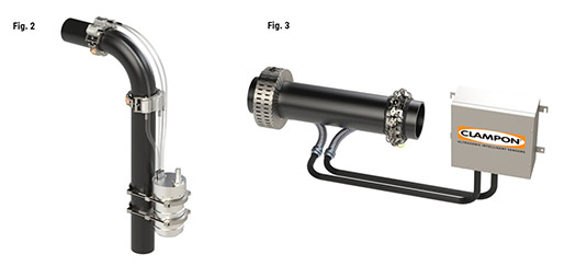
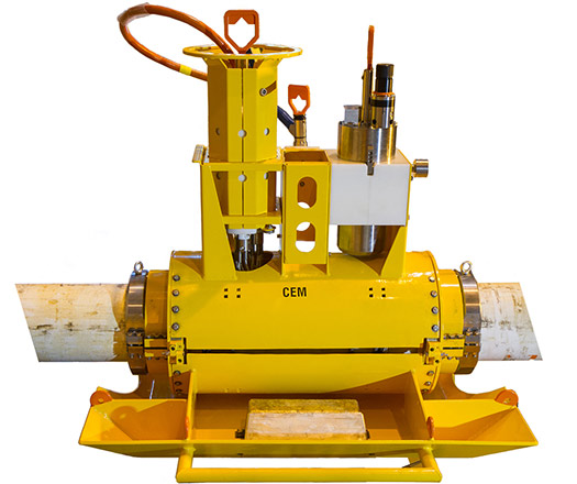
New instrument electronics were required to operate the EMATs, resulting in two generations of “CEMAT” electronics platforms to date. A subsea version of the instrument was released soon after the introduction of the EMAT technology. The current ClampOn Subsea CEM (Fig. 2) operates up to 16 transducers and is a self-contained wall thickness transmitter with electronics in an optionally ROV-retrievable atmospheric chamber.
Several engineering versions have been developed to fit various modules and pipelines, for wired and battery-powered operation, and for various modes of installation. The topside version (Fig. 3) of the instrument accommodates up to 32 transducers in Zone 1 hazardous locations, with a computer or automation controller in a safe area as part of the system. The instrument is installed permanently to monitor a pipe or elbow section with typical length of 0.5 m to 1.0 m, depending on pipe dimensions.
Wall thickness mapping by guided wave tomography. The mean wall thickness losses between pairs of acoustic transducers are monitored continuously and logged by the instrument and typically in the SCADA (supervisory control and data acquisition) system of the plant. Transducer pairs are combined flexibly for redundant wall area coverage. Partially overlapping sensitivity areas, due to a diverse set of guided-wave propagation paths (between transmit-receive transducer pairs), can be combined to generate a map of wall thicknesses across the monitored area.
The CorrPRINT™ tomography software package was developed in the 2010s to generate such wall thickness maps onboard the Subsea CEM and in the safe-area computer or automation controller accompanying topside instruments. This can supplement or replace the instrument output with key data, such as the thicknesses and positions of wall thickness minima.
The ClampOn CEM and the CorrPRINT™ tomography software combine into a highly scalable system. Systems with just a few transducers can be set up to primarily monitor the mean wall thicknesses across guided-wave propagation paths. The recorded wall thickness trends for each transducer pair can be post-processed interactively to produce wall thickness maps based on the available data.
At the other end of the scale, full-size systems can be set up with 16 or 32 transducers, providing monitoring data from hundreds of wave propagation paths. Acoustic guided waves follow the shortest path between each transmitter-receiver pair but also propagate along helically shaped paths around the pipe circumference. This way, a single pair of transducers can produce monitoring data from typically up to five signal propagation paths. Potentially, very large sets of acoustic data can be processed by on-board CorrPRINT™ software and reduced to a wall thickness map and key values based on it, for final transfer to an operator station and/or SCADA.
BURIED CORROSION MONITOR: FIELD CASE
ClampOn CEM® (Corrosion-Erosion Monitor) was selected for integrity monitoring of buried pipes at a location in the Gulf region. The instrument was installed underground with cabling to a cabinet with solar power and radio telemetry. The ClampOn CEM® was selected, due to its large 360o coverage area, resolution, performance and cost.
Site-specific challenges included underground installation, solar power, and system integration over a radio link. The radio telemetry and solar power solutions were contracted locally to ensure local service and maintenance. It was important for the project to have local knowledge for quick mobilization and understanding of the system, something that is too often forgotten in projects where equipment is imported.
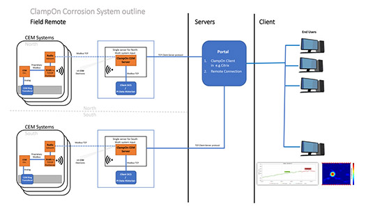
The telemetry solution offered a transparent link, which was selected to minimize the equipment in the field. This made it possible to avoid a computer or automation controller on the solar-powered field side of the system, maximizing reliability and making remote support from ClampOn easier, if requested. The setup (Fig. 4) is based on two-way TCP-IP Modbus communication from the instrument, via radio link, to servers running ClampOn Server software. Processed data are output to the client control system over Modbus or OPC DA. ClampOn Client software can be used to interface with the servers from an operator station or remotely; for example, in a Citrix secure environment. In this case, all data are processed and maintained within the client’s systems.
The dry-contact EMAT transducers (Fig. 5) of the Topside CEM® are mounted on coating with thickness up to 1 mm. Some of the pipes in this installation case had thicker coating, which was milled to 1 mm in the areas to be monitored.
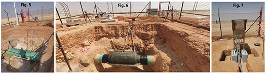
To protect the transducers from rock, dirt and silt we selected a fiberglass composite enclosure (Fig. 6) that is custom-made to fit the pipe sizes and sealed with a viscoelastic compound. A draining solution was included in case the enclosures are filled with water. Cabling is brought to the surface via a flexible metal conduit into the CEM® Head unit (data collection of raw acoustic signals).
Radio communication, solar panels, and battery system were selected locally, based on client preferences and history. ClampOn needed to integrate the instrument with these components and provide power consumption data for the desired mode of operation, Fig. 7. In this case, we selected a schedule of 6 measurements per day, easily changed in the future by accessing CEM® Server.
SUCCESSFUL SUBSEA CEM® INSTALLATION FROM PIPE LAYING VESSEL
ClampOn Subsea CEM® was installed (Fig. 8) during pipe laying and submerged as a part of the pipeline.
Subsea installations of the CEM® are plentiful, but installation from a pipe-laying vessel requires the instrument to tolerate bending and twisting of the pipe during deployment. A clever rotating protective cover made this possible.
The complete unit was installed topsides onboard the pipe-laying vessel (Fig. 9) during regular operation, and then lowered to the seabed (Fig. 10) as part of the pipeline. It is now monitoring corrosion on a large gas export line in the North Sea, Fig. 11. As it is located far from the shore and from other infrastructure, the system operates stand-alone with rechargeable battery packs. The monitoring data are logged to a memory within the ROV-exchangeable battery unit, combining the operation of changing battery and retrieving data.
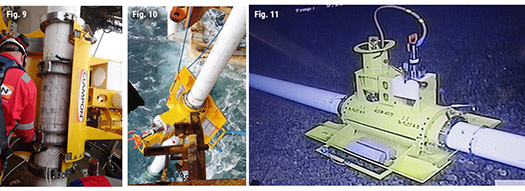
(Fig. 9-11) Installation on board pipe-laying vessel. The transducers are clamped to the pipe under the rotating protection cover and operated from the electronics canister. The protection cover can rotate 180o to land upright on the seabed. (left) Subsea CEM® during deployment. The protection cover has protected the transducers, electronics and battery from damage while sliding overboard the stern of the pipe laying vessel. (middle) ClampOn CEM® successfully installed on the seabed. The rotating protection cover serves as platform for the electronics and battery canister. (right)
For more information:
ClampOn Corrosion-Erosion Monitor, Topside and Subsea
https://www.clampon.com/products/topside/topside-corrosion-erosion-monitor/
https://www.clampon.com/products/subsea/subsea-corrosion-erosion-monitor/


- A Baker Hughes executive assesses the electrification effort (May)
- Nova Scotia’s Premier aims to revive province’s oil and gas activity (May)
- First Oil: OTC soldiers on for another year (May)
- OTC recognizes 2026 Spotlight on New Technology® Award winners (April)
- Umbilical‑less subsea completions: Reduced interface risk with eROCS and OTHOS (April)
- A deep understanding of flow patterns and pressure fields (April)

